8 en | Wiring Powered loop interface
2018.06 | 4.0 | F.01U.036.340 Installation instructions Bosch Security Systems, Inc.
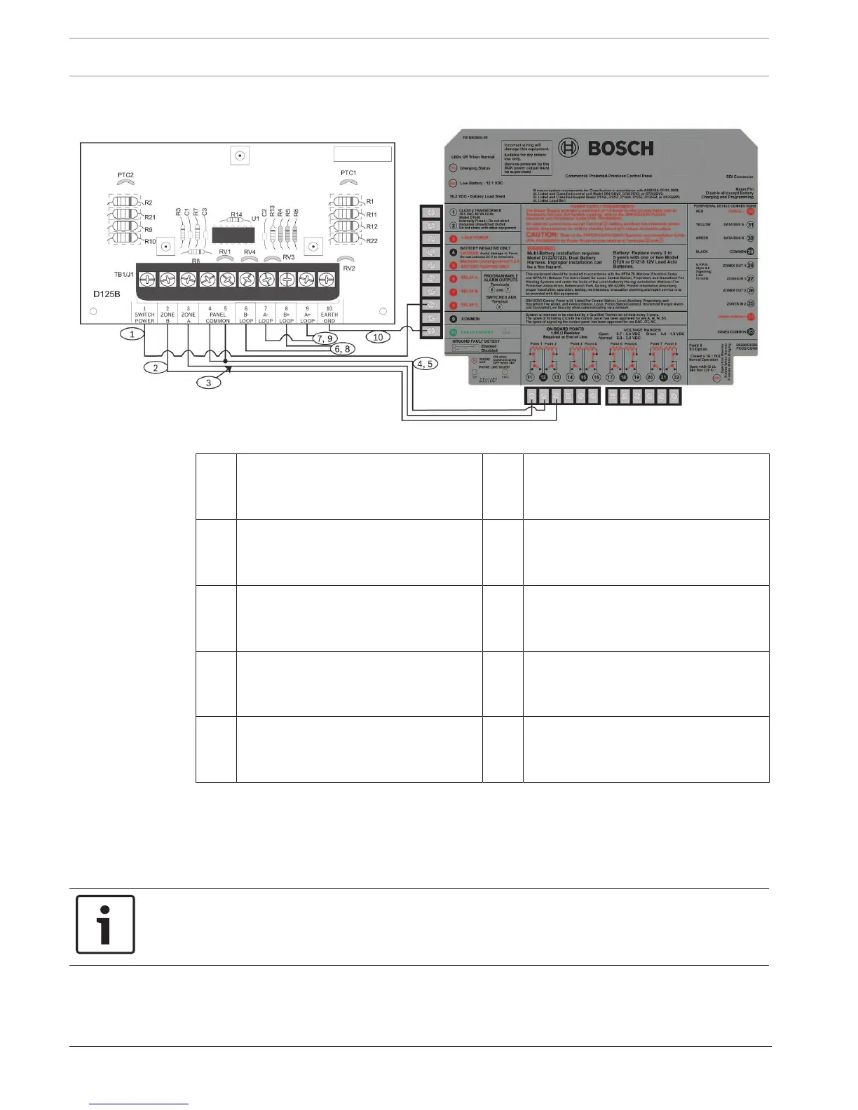
5.2.2 Wiring a G Series panel
Figure5.3: Wiring two-wire loops powered by a G Series panel
1 Power‑limited, supervised switched
auxiliary power from the control
panel’s relay C
2 Supervised connection to Zone B
power from an on‑board point of the
panel
3 Supervised connection to Zone A
power from an on‑board point of the
panel
4 Connection with terminal 4 to only one
common on the panel
5 Connection with terminal 5 to only one
common on the panel
6 Power-limited, supervised negative to
B loop detectors (see Wiring sensor
loops, page 6)
7 Power-limited, supervised negative to
A loop detectors (see Wiring sensor
loops, page 6)
8 Power-limited, supervised positive to B
loop detectors (see Wiring sensor
loops, page 6)
9 Power-limited, supervised positive to A
loop detectors (see Wiring sensor
loops, page 6)
10 Earth ground
5.3 Wiring for 12VDC or 24VDC power supplied by an external
power supply
Use either a 12VDC or 24VDC regulated, power‑limited auxiliary power supply listed under
UL864 or UL1481.
Notice!
Do not mix 12VDC and 24VDC detectors on the same module.