Powered loop interface Specifications | en 11
Bosch Security Systems, Inc. Installation instructions 2018.06 | 4.0 | F.01U.036.340
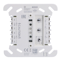
9 Power-limited, supervised positive to A
loop detectors (see Wiring sensor
loops, page 6)
10 Earth ground
11 Power‑limited, supervised switched
auxiliary power from the control
panel’s relay C to the switching relay
12 For 24V applications, cut this wire
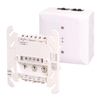
13 Negative connection from the auxiliary
power supply to the negative terminal
of the relay and panel common
14 Positive connection from the auxiliary
power supply to the positive terminals
of the relay
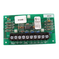
15 UL Listed regulated, power‑limited auxiliary power supply (12VDC or 24VDC) for fire
protection systems
6 Specifications
Electrical
12VDC 24VDC
Nominal operating voltage Supplied by the control panel
or by a regulated,
power‑limited 12VDC power
supply listed under UL864 or
UL1481
Supplied by a regulated,
power-limited 24V power
supply listed under UL864 or
UL1481
Alarm Current (maximum)
– One loop only 75 mA 168 mA
– Both loops 145 mA 300 mA
Standby Current (maximum)
– One loop only 12 mA 25 mA
– Both loops 24 mA 50 mA
Electrical - two‑wire powered loop ClassB
Current 12VDC 24VDC
– Alarm > 11.8mA > 24.1mA
– Detector 3mA 7mA
– Trouble < 3.5mA < 7.5mA
Loop wire resistance 50Ω 50Ω
Environmental
Environment Indoor, dry
Operating Temperature +32°F to +122°F (0°C to +50°C)
Relative Humidity 5% to 93% at +86°F (+30°C); non-condensing