6 en | Wiring Powered loop interface
2018.06 | 4.0 | F.01U.036.340 Installation instructions Bosch Security Systems, Inc.
5 Wiring
5.1 Wiring sensor loops
The D125B has two loop inputs:
Loop A Loop B
A+ (terminal 9) B+ (terminal 8)
A- (terminal 7) B- (terminal 6)
Notice!
Observe polarity when wiring detection loops. Do not cross Loop A and Loop B connections.
To supervise the loops, install an end-of-line (EOL) resistor after the last detector of each
protective loop. When installing a D125B in a new or existing system, use the 1.8kΩ EOL
resistor (P/N: F01U009011B) supplied with the module.
Notice!
To ensure system supervision, do not use looped wire under the terminals. Break the run to
provide supervision of the connections.
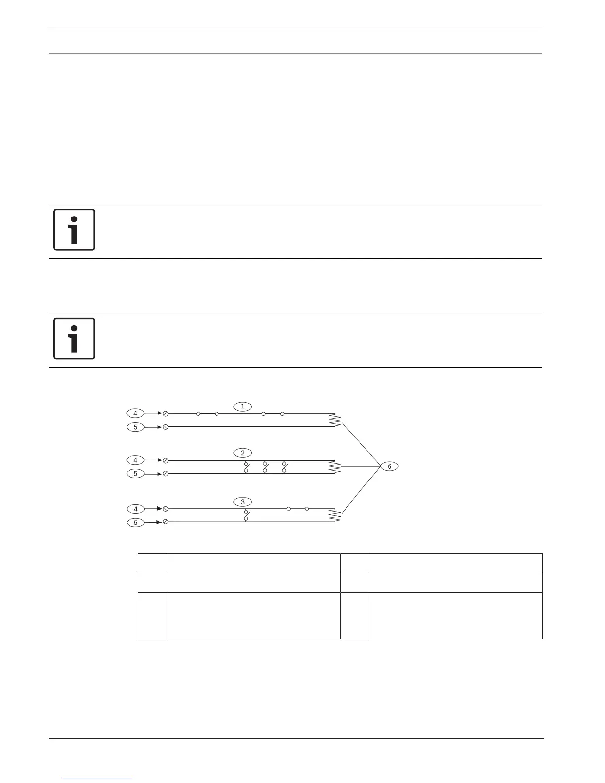
Figure5.1: D125B loop wiring
1 Normally‑closed contacts (NC) 4 Point input terminal
2 Normally‑open contacts (NO) 5 Common
3 Combination: Normally‑open and
normally‑closed contacts (NO/NC)
6 1.8 kΩ EOL resistor (P/
N:F01U009011B) supplied with the
module
The D125B shorts the protective loop on the control panel when the high (+) and low (-) side
of either module loop is shorted together or when a smoke detector activates. The module
opens the protective loop on the control panel during the following conditions:
– The module protective loop is opened.
– The D125B is not powered.