1 689 989 473 | 2021-08-24Robert Bosch GmbH
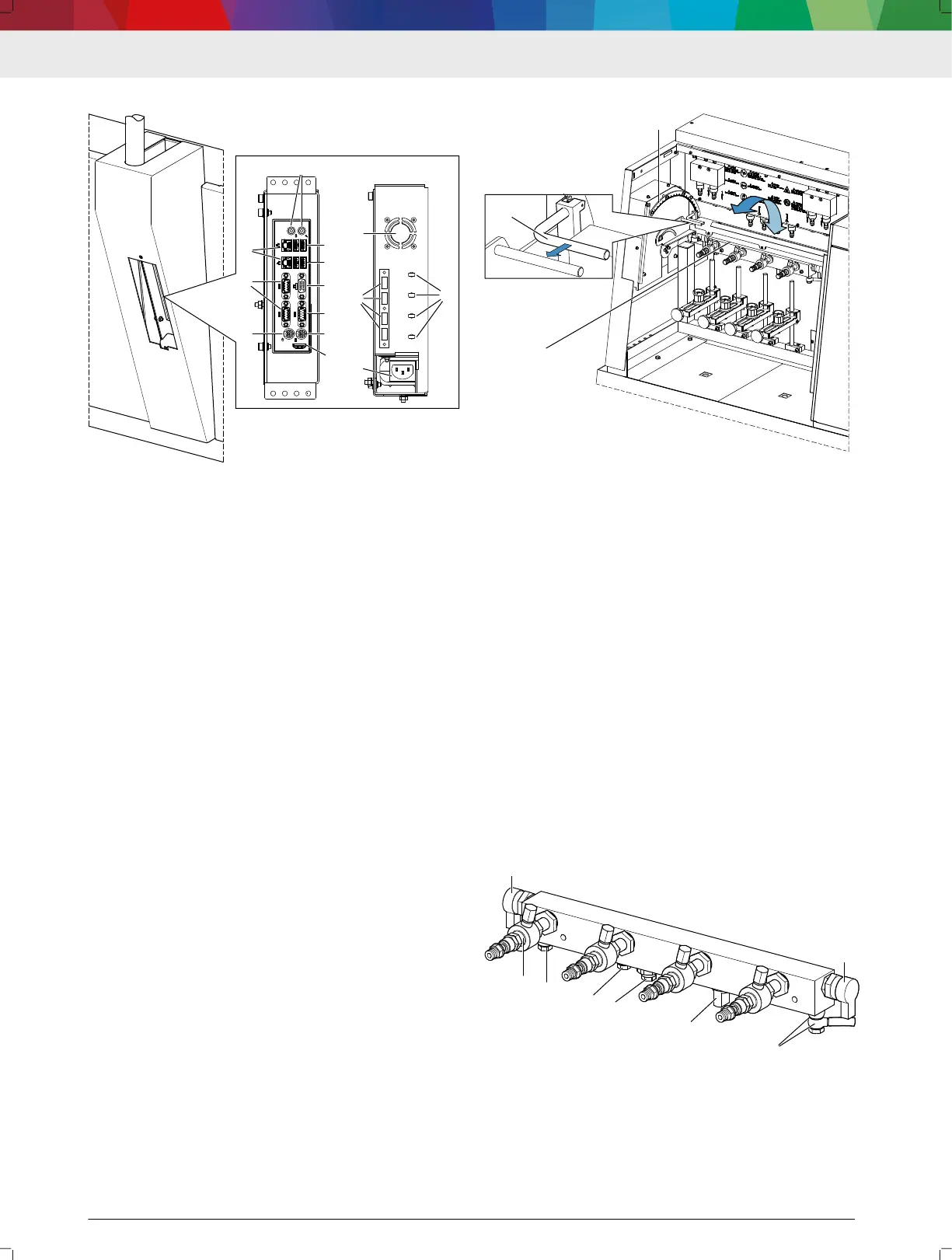
3.8.2 Computer unit
USB
USB
HDMI
458922-62_Pal
1
2
3
4
5
6
7
8
7
1
9
10
11
12
9:
Computer unit connections
(1) Serial interface (RS232)
(2) Monitor connection (VGA)
(3) Network connection (RJ45)
(4) USB 3.0 ports
(5) USB 2.0 ports
(6) Microphone and headphone port
(7) Mouse, keyboard
(8) HDMI
(9) Vent grille
(10) USB add-ons
(11) Voltage supply (power supply unit)
(12) Cable holder
The operating system, the "DDM" software and the
"DCI" software are installed on the computer unit. The
Windows rewall and virus scanner are activated to
protect against attacks from the Internet.
The computer unit is connected to the actuation unit
and the monitor. The USB ports on the front provide
the ability to connect additional USB devices, e.g. a
USB stick. The DCI 700 is connected to the Internet via
the network connection.
---Separator---
3.8.3 Swivel xture with high-pressure rail
10:
Swivel xture
(1) Swivel fixture with high-pressure rail
(2) Locking lever
(3) Scale plate
The injectors connected to the high-pressure rail are
placed in the vertical position with the aid of the swivel
xture (1). The injection chambers are mounted on the
injectors in this position and the injectors connected
electrically and hydraulically. The swivel range of the
swivel xture is 0° to 90°.
The marking "P" (rearmost position) on the scale plate
(3) marks the position "P". The injectors are connected
to or removed from the high-pressure rail in this posi‐
tion. In addition, the inlet lter and the connecting ca‐
bles for the injectors are accessible in position "P".
To swivel, pull the locking lever (2). After the locking
lever has been released, place the swivel xture (1) in
the desired position. Once the desired position has
been reached, release the locking lever and allow the
detent to engage the scale plate (3).
---Separator---
3.8.4
High-pressure rail
11: High-pressure rail
(1) Pressure control valve K20
(2) High-pressure connection, position "A", with blind plug
(3) Hose fitting for return quantity
(4) Port for additional sensors and components
(5) Pressure limiting valve
(6) Rail pressure sensor
(7) Pressure control valve K30
DCI 700 | 9 | en
 Loading...