Do you have a question about the Bosch DINION IP 4000i IR and is the answer not in the manual?
Illustrates NPT thread sizes, mounting plate dimensions, and hardware compatibility for installation.
Details essential camera controls and outputs including Reset button, Menu access, and Video Out service port.
Depicts various connection types: Ethernet (PoE), CVBS, Audio In/Out, Alarm, and 12 VDC/24 VAC power inputs.
Provides detailed color-coded wiring instructions for Audio, Alarm, and Video signals, including grounding.
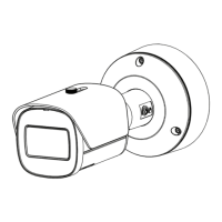
Illustrates the physical attachment and adjustment of the camera using a T15 tool and mounting screws.
Details the Pan, Tilt, and Twist adjustments for camera positioning, including 360° rotation and 90° tilt.
Guides users on downloading and installing the IPHelper software for initial device setup and network configuration.
Explains how to access and use the Lens Wizard within the Installer Menu for camera lens setup and calibration.
Details the process for adjusting zoom and focus using the camera's menu or specific buttons for optimal imaging.
Provides instructions for using Bosch Video Client and Configuration Manager for viewing and managing the camera.
| Ingress Protection | IP66 |
|---|---|
| Camera Type | Bullet |
| Environment | Outdoor |
| Vandal Resistant | No |
| Frame Rate | 30 fps |
| IP Rating | IP66 |
| IR Range | 30 m |
| Compression | H.265, H.264, MJPEG |
| Power Supply | PoE (IEEE 802.3af) or 12 V DC |
| IR Distance | 30 m |
| Sensor Size | 1/3 inch |
| Focal Length | 2.8 mm |
| Field of View | 32° - 92° |
| Minimum Illumination | 0.05 lux |
| Operating Temperature | -30°C to +50°C |