DS484Q/DS486Q | Installation Instructions | 4.0 Setup and Alignment
12 Bosch Security Systems, Inc. | 7/05 | 4998138530F
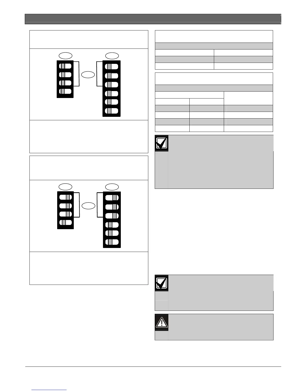
Figure 17: Transmitter and Receiver DIP Switch
Settings – One Set
1
2
3
1 - Transmitter DIP Switches with original settings
(Group A, Channel M)
2 - Receiver DIP Switches with original settings
(Group A, Channel M)
2 - DIP Switches 1, 2, and 3
Figure 18: Example of Transmitter and Receiver
DIP Switch Settings – Two or More
Sets
1
2
3
1 - Transmitter DIP Switches set for Group B,
Channel 3
2 - Receiver DIP Switches set for Group B,
Channel 3
2 - DIP Switches 1, 2, and 3
Set DIP Switches 1, 2 and 3 to OFF or ON on each
transmitter and receiver, according to the desired
group and channel selections. Refer to Table 7 and
Table 8 for the DIP Switches 1, 2, and 3, and the
example for Group B, Channel 2 in Figure 18.
Table 7: Group Selection
DIP Switch 1 Group
OFF A
ON B
Table 8: Channel Selection
DIP Switch
2 3
Channel
OFF OFF M
OFF ON 1
ON OFF 2
ON ON 3
One transmitter and one receiver facing
each other are a set. In a set, each unit
must have the same setting for group and
for channel.
When installing two or more sets, use
different settings for each set (transmitter
and receiver) to avoid incorrect
communication.
4.1.4 Synchronized Wiring
Synchronized (abbreviated “synchro”) wires are
required when installing two or more sets in the same
group by using the SYNCHRO terminal on each
transmitter. Synchro wires are not required between
the receivers.
The synchro wire should be more than 0.8 mm
(22 AWG) in diameter, run no longer than
20 m (66 ft), and be wired only to the same group
(Group A to Group A or Group B to Group B). Do not
wire across groups (Group A to Group B).
Synchronized transmitters must use a common power
supply.
The system does not activate when synchro
wires are connected improperly, or if other
unneeded wires are connected.
The POWER LED flashes when the
required wires are not connected correctly.
When the POWER LED flashes, shut off
the power and reconnect the wires
correctly.