DS484Q/DS486Q | Installation Instructions | 3.0 Wiring
8 Bosch Security Systems, Inc. | 7/05 | 4998138530F
3.0 Wiring
Apply power only after all connections are
made and inspected.
Install these detectors according to the
National Electrical Code, NFPA-70.
Table 7 is based on one set (transmitter and receiver)
connected to the same wire run from the power source.
When installing two or more sets on one wire run,
calculate the maximum length by dividing the
maximum listed wire length by the number of sets
installed.
Connect the transmitters and receivers to a UL Listed
power supply or control panel capable of providing
standby power for at least 4 hours.
Test this system at least once a week to ensure proper
operation.
Table 3: Wire Length / AWG Chart
Maximum Distance [m (ft)]
DS484Q DS486Q
Wire
Gauge
[mm
2
(AWG)]
12 VDC 24VDC 12VDC 24VDC
0.8
(22)
90
(295)
850
(2789)
80
(295)
730
(2395)
1.06
(19)
180
(591)
1670
(5479)
150
(492)
1420
(4659)
1.37
(17)
330
(1083)
3020
(9908)
280
(919)
2580
(8465)
1.8
(14)
590
(1936)
5370
(17618)
500
(1640)
4570
(14993)
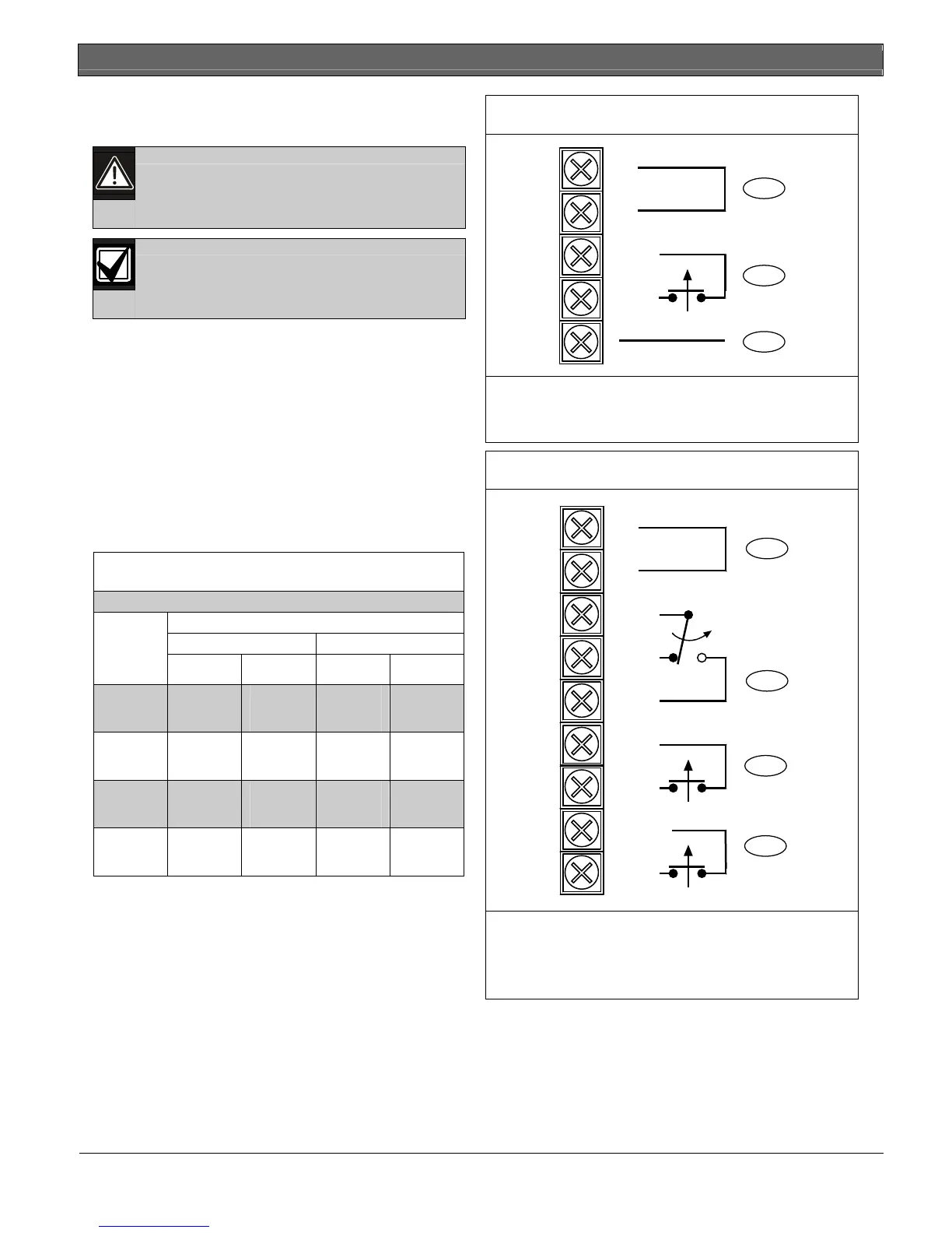
Figure 10: Transmitter, Terminal Block Wiring
1
2
3
+
-
COM
NC
1 - Power (non-polarized), 10.5 VDC to 28.0 VDC
2 - Tamper Output (1b), 30 VDC 0.1 A
3 - Synchronized wiring
Figure 11: Receiver, Terminal Block Wiring
4
3
1
2
+
-
COM
NC
NO
EDC
NC
TAMPER
NC
1 - Power (non-polarized), 10.5 VDC to 28.0 VDC
2 - Alarm Output (1c), 30 VDC 0.2 A
3 - EDC Output (1b), 30 VDC 0.2 A
4 - Tamper Output (1b), 30 VDC 0.1 A