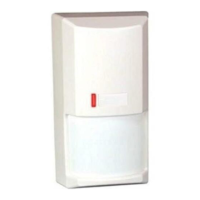
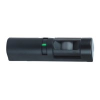
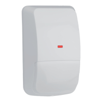
Installation Instructions
for the DS820 Series
TriTech Microwave/PIR Intrusion Detectors
1.0 Specifications
• Dimensions (HxWxD): 5 in. x 2.8 in. x 2.2 in.
(12.7 cm x 7.1 cm x 5.6 cm)
• Input Power: 9 to 15 VDC, 16 mA DC nominal
(up to 48 mA DC during walk testing
or trouble conditions). Use only an
Approved Limited Power Source.
• Standby Power: No internal standby battery.
Standby power must be provided by
an Approved Limited Power Source.
Sixteen mAh required for each hour of
standby time needed. For UL Listed
Requirements, four hours (64 mAh)
minimum are required.
• Alarm Relay: Silent-operating Normally Closed
reed relay. Contacts rated 3 watts,
125 mA, 28 VDC maximum for DC
resistive loads; and protected by a
4.7 ohm, ½ watt resistor in the
common "C" leg of the relay. To be
connected to a SELV (Safety Extra-
Low Voltage) circuit only. Do not use
with capacitive or inductive loads.
• Tamper: Normally Closed (with cover on).
Contacts rated at 28 VDC, 125 mA
max. To be connected to a SELV
(Safety Extra-Low Voltage) circuit only.
Connect tamper circuit to a 24-hour
protection circuit.
• Temperature Range: -40°F to +120°F (-40°C to +49°C).
For UL Listed requirements, the
temperature range is +32°F to +120°F
(0°C to +49°C), indoor use.
• Microwave Frequency:
DS820: 10.525 GHz (UL Listed)
DS820A: 10.687 GHz (Export Only, not UL
Listed)
DS820B: 9.9 GHz (Export Only, not UL
Listed)
• Coverage: 20 ft. by 20 ft. (6.1 m by 6.1 m)
• Internal Pointability: +2° to –10° Vertical, ±10° Horizontal.
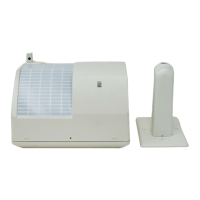
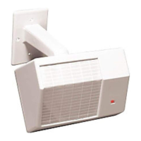
• Options: B328 Gimbal Mount Bracket,
B335 Low Profile Swivel Mount
Bracket, B338 Ceiling Mount
Bracket
NOTE: Use of a bracket may reduce range and increase dead
zone areas; not recommended for installations containing
pets.
•
Reading Bosch Security Systems, Inc. Product Date Codes
For Product Date Code information, refer to the Bosch Security
Systems, Inc. Web site at: http://www.boschsecurity.com/
datecodes/
• Compliance: This device complies with Part 15 of the FCC
Rules and with RSS-210 of Industry and Science Canada.
Operation is subject to the following two conditions:
(1) this device may not cause harmful interference, and
(2) this device must accept any interference received,
including interference that may cause undesirable
operation.
Changes or modifications not expressly approved by Bosch
Security Systems can void the user’s authority to operate the
equipment.
2.0 Installation Considerations
• Never install the detector in an environment that causes an
alarm condition in one technology. Good installations start with
the LED OFF when there is no target motion. It should never be
left to operate with the tri-color LED in a constant or intermittent
green, yellow, or red condition.
• Point the unit away from outside traffic (roads/alleys).
NOTE: Microwave energy will pass through glass and most
common non-metallic construction walls.
• Avoid installations where rotating machines (e.g. ceiling fans)
are normally in operation within the coverage pattern. Point the
unit away from glass exposed to the outdoors and objects that
may change temperature rapidly.
NOTE: The PIR detector will react to objects rapidly changing
temperature within its field-of-view.
• Eliminate interference from nearby outside sources.
3.0 Mounting
• Select a location likely to intercept an intruder moving across
the coverage pattern. The surface should be solid and
vibration-free. Mounting height range is 6 to 8 feet (1.8 to
2.4 m). Recommended mounting height is 6.5 feet ( 2 m).
• Remove the cover. Insert a flathead screwdriver into the locking
tab hole at the bottom front of the detector. Pull the cover up
and forward.
Vertical
Adjust
Screw
Tri-color
LED
Terminal
Strip
LED
On/Off
Pins
MW
0°
- 4°
- 8°
On
Off
Microwave
Range Adjust
PIR
Sensitivity
Selection Pins
Vertical Adjust
Scale
Look Down Lens
MIN M AX
Face of Lens
(masking area)
Corner Mount
Knockout (4)
Surface Mount
Knockout (2)
Wire
Entrances
Bracket Mount
Knockout
Vertical Adjust
Screw Mount
Cover Tab and
Locking Screw Hole
Wire
Entrances
• Remove the circuit board from the base. Loosen the Vertical
Adjust Screw and slide the circuit board down, then out.
• Break away the appropriate thin-wall wire entrance and
mounting hole coverings in the base.
• Using the base as a template and aligning it so that the
detector will be mounted with the terminal block at the top and
the PIR lens at the bottom, mark the location of the mounting
holes on the mounting surface. Pre-start the mounting screws.
• Route wiring as necessary. Route to the rear of the base and
through the wire entrance. Make sure all wiring is unpowered
before routing.