90 en | Maintenance FAS-420-TM Aspirating Smoke Detector
F.01U.088.878 | 4.1 | 2010.11 Operation Guide Bosch Sicherheitssysteme GmbH
7.7 Blowing-out Process for the Pipe System
The blast air supply (compressor or mobile blowing-out system) required for the blowing-out
process for the pipe system must be connected via the quick lock coupling fitting to the three-
way tap on the pipe system.
A check valve for relieving pressure from the pipe system must be fitted to the end of each
pipe branch. The check valve prevents damage to the air sampling openings and prevents dirt
deposits from being blown through the pipe system. To prevent aspiration reducing film
sheets in deep-freeze areas from tearing, it is advisable to use special deep-freeze aspiration
reductions.
The manual blowing-out process on the pipe system is carried out as follows (see Figure 7.4):
1. Position the tap lever so that the blast air and pipe system are connected (B-C
connection).
The connection to the FAS-420-TM must be blocked for blowing-out!
Manually blow out the pipe system for approximately 10 seconds.
2. Set the lever of the tap such that the device is not connected with the pipe system or
with the connection for the blast or compressed air supply. Wait approximately 20
seconds so that dust and dirt raised in the pipe system can settle and thus will not be
sucked through the aspirating smoke detector.
3. Reconnect the blown-out pipe system to the FAS-420-TM within a further 10 seconds by
switching over the tap accordingly (A-C connection).
7.8 Checking the Airflow Sensor Calibration
Check the airflow sensor value with the diagnostic software.
Functional principle
During initialization of the connected pipe system, the device saves the measured actual value
of the airflow as a target value via the integrated airflow monitoring. This nominal value then
serves as a reference value for the additional evaluation of a possible airflow malfunction.
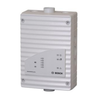
Figure 7.4 Installing the three-way tap
1 Blast air/compressed air
connection
2 Pipe system connection
3 Aspirating smoke detector
connection
4 Air filter (optional)
F
A
S
-
4
2
0
-
T
M
s
e
r
i
e
s
A
B
C
1
2
3
4
A
B
C
2.
A
B
C
3.
A
B
C
1.
 Loading...


