18 en | Accessories Conventional Automatic Detectors
F.01U.002.707 | 8.0 | 2011.10 Operation Guide Bosch Sicherheitssysteme GmbH
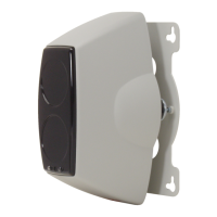
5.7.1 Remote Indicator FAA-420-RI
Installation Notes
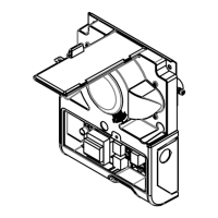
Figure 5.1 Mounting the FAA-420-RI
1. Remove the hood from the baseplate prior to installation. To do so, press on the snap-fit
hook with a flat object (e. g. screwdriver) and carefully lift off the hood.
2. Install the FAA-420-RI on a dry and even ceiling or wall.
3. In the case of surface mounted cable feed, break off the pre-punched cable entries (refer
to Figure 5.1, item Z) from the housing.
In the case of flush mounted cable feed, insert the cable through the opening (refer to
Figure 5.1, item Y) below the connection board.
4. Refit the hood and click into place when installation and connection are complete.
Wiring
The FAA-420-RI is connected to two screw terminals.
All current Bosch fire detectors are equipped with an internal resistor to restrict current
consumption.
NOTICE!
The FAA-420-RI must be installed such that the broad side of the red alarm indication (A)
follows the observer’s line of sight.
Terminal Connector
- GLT - / LSN -
+ GLT + / LSN +
1.
+
57
51
_
Y
A
X
31
Z
79
79
2.
FAA-420-RI
A
+
_
CAUTION!
If the current consumption for the connected detector exceeds 20 mA, it can lead to the
malfunction of or damage to the FAA-420-RI Remote Indicator.You should restrict the
maximum detector current consumption to 20 mA to avoid damaging the FAA-420-RI.
 Loading...

