Installation diagram
The installation regulations provided in this quick reference guide are a guide
only. Please refer to the latest AS 5601/NZ 5621 edition and local authority
guidelines.
Natural draft
Bosch hot water systems with natural draft flue terminals
are: External and Internal HydroPower ranges as well as the
Pilot Ignition range.
P = Electricity meter or fuse box
W = Openable window
Shading indicates prohibited areas
for flue terminals
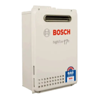
Fan assisted
Hot water systems with fan assisted flue terminals in the
Bosch product range are: Highflow range and Bosch 32 Series.
Installation regulations5
Minimum clearance of flue terminals5.1
T = flue terminal
I = Mechanical air inlet
M = Gas meter