Item
Minimum
Clearance (mm)
Natural Draft
Minimum
Clearance (mm)
Fan Assisted
a
Below eaves, balconies and other projections
Appliances up to 50 MJ/h input 300 200
Appliances over 50 MJ/h input 500 300
b From the ground, above a balcony or other surface* 300 300
c From a return wall or external corner* 500 300
d From a gas meter (M) 1000 1000
e From an electricity meter or fuse box (P) 500 500
f From a drain pipe or soil pipe 150 75
g
Horizontally from any building structure or obstruction facing a
flue terminal
500 500
h From any other flue terminal, cowl, or combustion air intake* 500 300
j
Horizontally from an opening window, door, non-mechanical air
inlet. Or other opening into a building with the exception of sub
floor ventilation
Appliances up to 150 MJ/h 500 300
Appliances over 150MJ/h input up to 200 MJ/h input 1500 300
Appliances over 200 MJ/h input up to 250 MJ/h input* 1500 500
Appliances over 250 MJ/h* 1500 1500
All fan-assisted flue applications, in the direction of discharge – 1500
k From a mechanical air inlet, including spa blower 1500 1000
n
Vertically below an openable window, non-mechanical air inlet, or
any other opening into a building with the exception of sub-floor
ventilation:
Space heaters up to 50 MJ/h 150 150
Other appliances up to 50 MJ/h 500 500
Appliances over 50 MJ/h and up to 150 MJ/h input 1000 1000
Appliances over 150 MJ/h input 1500 1500
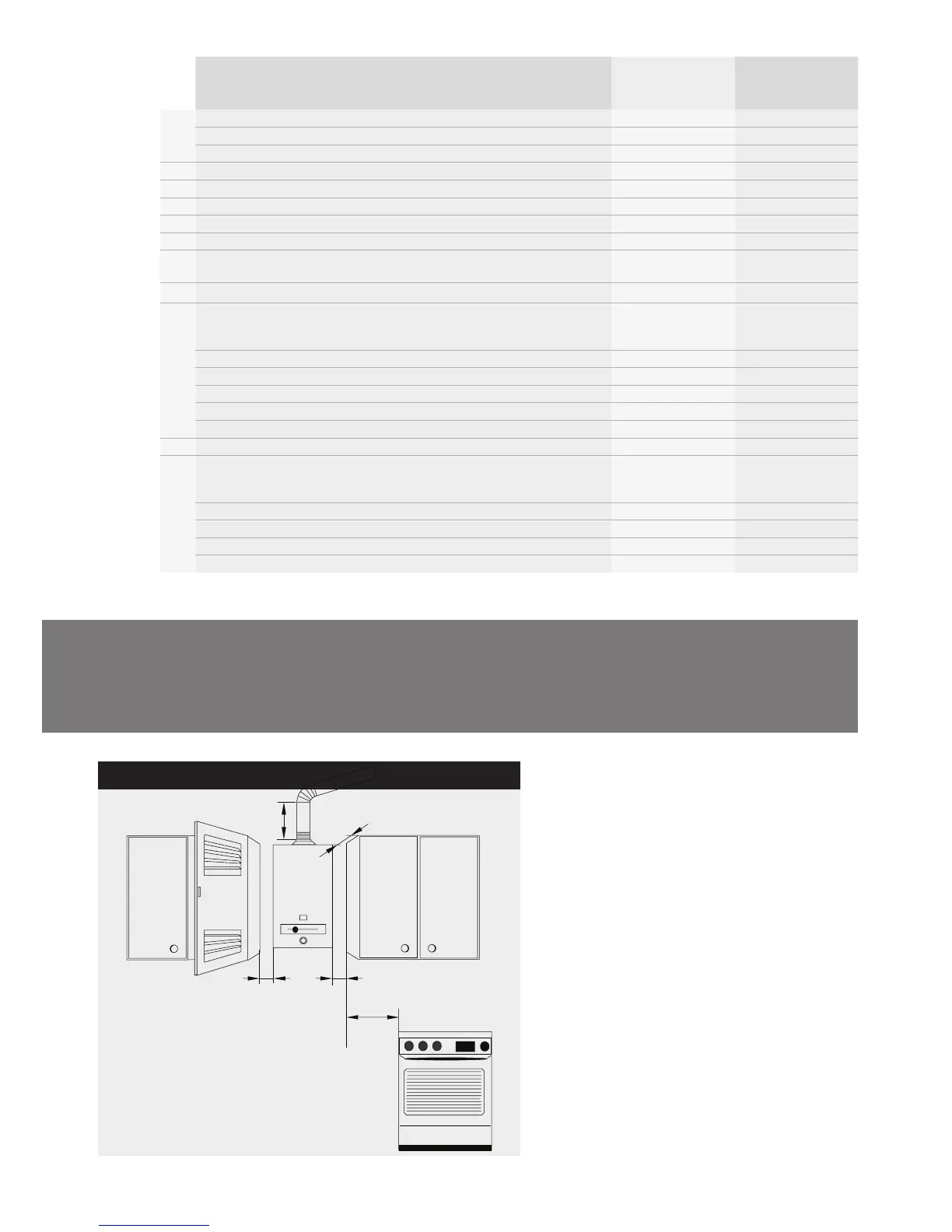
Installation locations for internal continuous
flow gas hot water systems
5.2
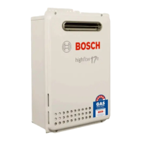
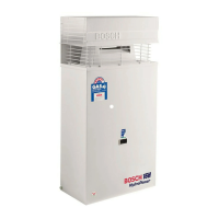
Internal continuous flow gas hot water systems in
the Bosch product range are: Internal HydroPower
range, internal installations of the 32 Series
(external installations also possible).
Please note that appropriate flueing is required for
internal installations. Prohibited internal installation
locations for instantaneous water heaters are:
bedrooms, bathrooms, toilet rooms, or combined
living/sleeping rooms. Please refer to AS 5601/NZ
5621, installation instructions, and local authority
guidelines.
This diagram of installation locations serves as a
guide only. Please refer to AS 5601/NZ 5621 and local
authority guidelines.
* Unless appliance is certified for closer installation.