6 720 680 226
Installation instructions
11
3.3.2 Vent specifications
Establish vent clearances that comply with the vent
manufacturer's specifications and all applicable
national/local codes.
Venting specifications
Condensate drain requirements
An external condensate drain (not supplied with the
heater) must be installed under the following
conditions:
• All vertical terminating vent installations.
• Horizontal terminating vent installations where the
total linear vent length is greater than 6 feet (1.8 m).
• Vent installations where any section of the exhaust
vent pipe passes through an unconditioned space.
Minimum combustion air and exhaust pipe
length
The minimum exhaust pipe length is 3 feet (1m) of
straight vent pipe. The minimum combustion air pipe
length is one 90° elbow.
Maximum combustion air and exhaust pipe
length
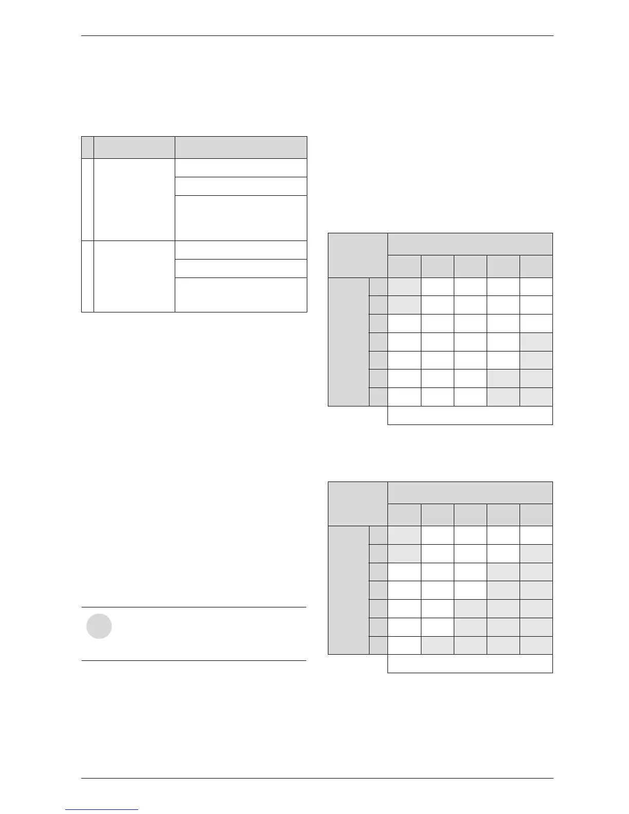
The following tables (Tables 5 & 6) display the
maximum allowable straight pipe lengths for
combustion air and exhaust piping with consideration to
the number of elbows used.
Step 1: If using the twin pipe penetration system, refer
to table 5. If using the concentric vent kit
system, refer to table 6.
Step 2: Total the number of 90° elbows and 45°
elbows used on the exhaust piping.
Step 3: Use this value in the appropriate table to
determine the maximum straight exhaust pipe
length allowed.
Step 4: Total the number of 90° elbows and 45°
elbows used on the combustion air piping.
Step 5: Use this value in the appropriate table to
determine the maximum straight combustion
air pipe length allowed.
* Not allowed. At least one 90º elbow required.
** Not allowed. Minimum of 3 feet (1m) of straight pipe required.
* Not allowed. At least one 90º elbow required.
** Not allowed. Minimum of 3 feet (1m) of straight pipe required.
Note: Include pipe length that is part of the concentric terminal.
Diam. Aproved terminals
E
x
h
a
u
s
t
3 or 4 inches
“T” terminal
90° elbow
Concentric
(196016)
I
n
t
a
k
e
3 or 4 inches
“T” terminal
90° elbow
Concentric
(196016)
Table 4 Venting specifications for intake and exhaust
Note: 90° elbows used for
terminations should not be counted
in the exhaust and combustion air
piping.
Twin Pipe
System
# of 90° elbows
0 1 2 3 4
# of 45°
elbows
0 N/A* 26 21 16 11
1 N/A* 23 18 13 8
2 23 20 15 10 5
3 20 17 12 7 N/A**
4 17 14 9 4 N/A**
5 14 11 6 N/A** N/A**
6 11 8 3 N/A** N/A**
Maximum allowable straight pipe length (ft)
Table 5 Maximum allowable straight pipe length (twin
pipe)
Concentric
pipe System
# of 90° elbows
0 1 2 3 4
# of 45°
elbows
0 N/A* 18 13 8 3
1 N/A* 15 10 5 N/A**
2 15 12 7 N/A** N/A**
3 12 9 4 N/A** N/A**
4 9 6 N/A** N/A** N/A**
5 6 3 N/A** N/A** N/A**
6 3 N/A** N/A** N/A** N/A**
Maximum allowable straight pipe length (ft)
Table 6 Maximum straight pipe length (concentric ter-
minal)