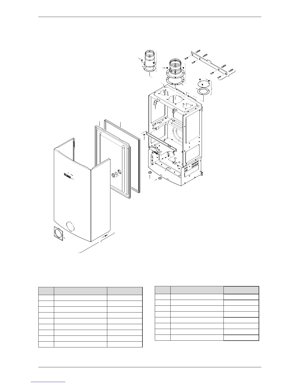
Item Description Reference
1 Front cover 8 705 431 369
2 Cover shield 8 705 506 749
3 Trade mark badge 8 701 103 140
4 Cover screw 8 703 401 170
5 Combustion cover 8 700 506 300
6 Combustion cover gasket 8 704 701 084
7 Observation window 8 705 600 003
8 Holding bracket 8 708 104 103
9 Screw 8 703 403 012
Table 21
10 Combustion cover clip 8 701 201 032
11 Grommet set 8 710 203 039
12 Exhaust accessory 8 705 504 152
13 Gasket exhaust 8 700 103 710
14 Inlet air cover 8 708 006 022
15 Inlet air gasket 8 700 103 166
16 Inlet air accessory 8 705 504 154
17 Mounting bracket 8 701 309 164
Item Description Reference
Table 21