6 720 680 226
18
Installation instructions
Adjusting minimum power fan speed (P2)
To select fan speed:
B Press ON/OFF button into OFF.
B Press and hold "Program" button and press
ON/OFF button to turn appliance ON.
Fig. 19
B As soon as '188' is displayed, release "Program"
button , and the display reads P2.
B Press to enter P2 adjustment. The current set-
ting will appear on the
display (factory default: 12).
B Press or to choose the fan speed suitable
with your installation, see table 12.
B Press and hold (± 5 sec.) “Program” button until
the display flashes, then the selected value is
memorized.
Adjusting maximum power fan speed (P1)
To select fan speed:
B Press ON/OFF button into OFF.
B Press and hold "Program" button and press
ON/OFF button to turn appliance ON.
Fig. 20
B As soon as '188' is displayed, release "Program" but-
ton , and the display reads P2.
B Press the minus button to display P1.
B Press “Program” button to enter P1 adjustment.
The current setting will appear on the display.
B Press or to choose the fan speed suitable
with your installation, see Table 12.
B Press and hold (± 5 sec.) “Program” button until
the display flashes, then the selected value is memo-
rized.
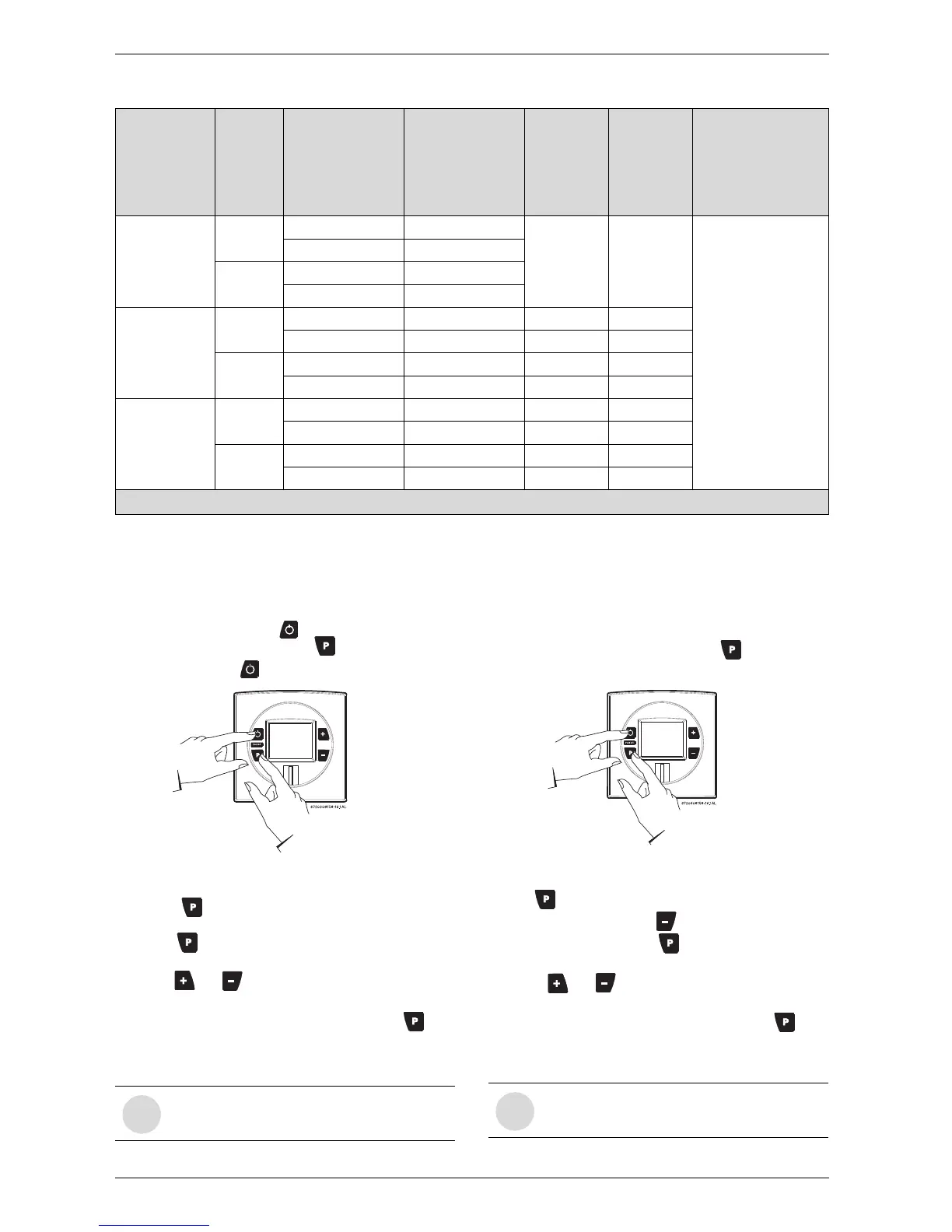
Natural
Gas
Liquid
propane
Altitude
(above sea
level)
Vent
terminal
Total equivalent
vent length
1)
Minimum power
fan speed (P2)
Maximum
power fan
speed (P1)
Maximum
power fan
speed (P1)
0 - 2000 ft
(0 - 610 m)
Concentric
8 - 25 ft 12
No
modification
required
No
modification
required
For operation at eleva-
tions above 2,000 ft
(610 m) the equip-
ment ratings shall be
reduced at the rate of
4% for each 1,000 ft
(305 m) above sea
level
26 - 46 ft 13
Twin
system
8 - 37 ft 12
38 - 62 ft 13
2000 - 4500 ft
(610 - 1372 m)
Concentric
8 - 25 ft 14* 52* 52*
26 - 46 ft 14* 53* 53*
Twin
system
8 - 37 ft 13* 52* 52*
38 - 62 ft 14* 53* 53*
4500 - 8000 ft
(1372 - 2439 m)
Concentric
8 - 25 ft 14* 53* 53*
26 - 46 ft 16* 53* 53*
Twin
system
8 - 37 ft 14* 53* 53*
38 - 62 ft 15* 53* 53*
* Above 2000 ft, CO
2
levels must be checked with a combustion gas analyzer, see section
6.5
for instructions.
Table 12 Fan speed adjustment
1) Full equivalent length (inlet + outlet piping + fittings)