6 720 680 226
Interior components diagram and parts list
59
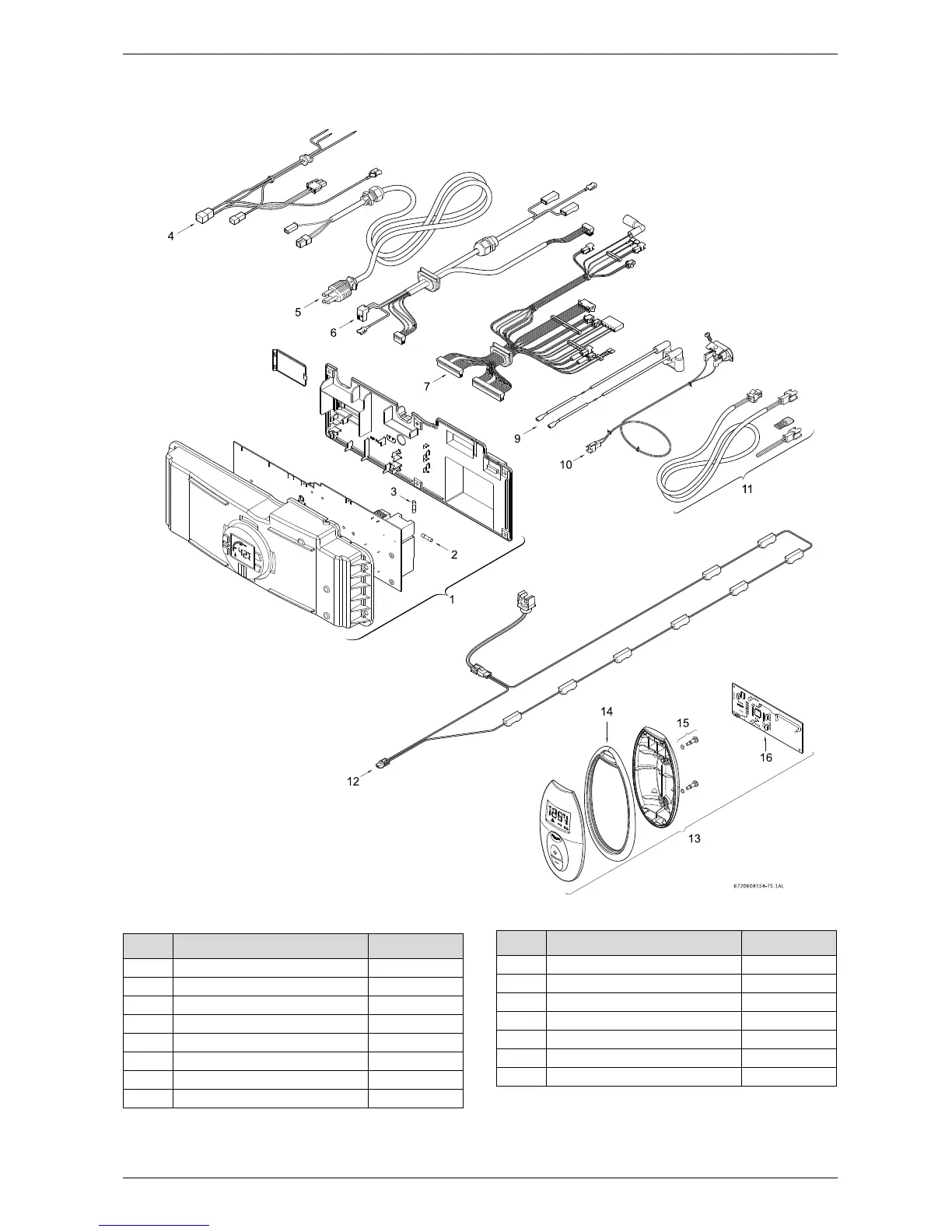
12.2.6 Group 6
Fig. 77 Components Diagram
Item Description Reference
1 Control unit 8 707 207 257
2 Fuse T2.5A 1 904 521 342
3 Fuse T1.6A 8 700 609 008
4 Power supply cables 8 704 401 371
5 Power supply cord 8 704 401 378
6 Fan cables 8 704 401 347
7 Wire harness 8 704 401 348
9 Electrode cables 8 704 401 346
Table 26
10 Flue gas limiter 8 700 400 032
11 Cascading kit (optional) TLINK
12 Freeze prevention kit 7 709 003 665
13 Remote control TSTAT2
14 Shaped seal 8 700 201 012
15 Screw 8 703 401 109
16 Printed circuit transciever 8 708 300 123
Item Description Reference
Table 26