14
Commissioning
MP 100 – 6721819201 (2020/02)
System components:
230 V AC Mains voltage
BUS BUS system EMS 2/EMS plus
CON Control unit EMS 2/EMS plus
HC1... Heating circuits
HS Heat Source
MC1 External swimming pool control unit (optional); if
there is no swimming pool control unit, connect
jumper to terminal MC1 ( Fig. 1 [2] at end of
document)
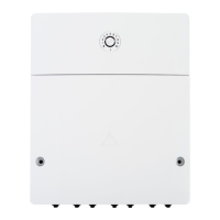
MP 100 Module MP 100
TC1 Swimming pool temperature sensor
VC1 Mixing valve motor
4 Commissioning
First make all electrical connections and then carry out the
commissioning!
▶ Observe the installation instructions for all components
and assemblies in the system.
▶ Only switch on the power supply after all modules are set
up.
1. If necessary, set the coding switch on other modules. The
coding switch on the module MP 100 has no function.
2. Connect the entire system to the mains voltage.
Once the status indicator on the module lights up green
constantly:
3. Put the control unit into operation as described in the
accompanying installation instructions and make the
appropriate settings.
5Troubleshooting
Use only original spare parts. Damage caused by the use of
spare parts not supplied by the manufacturer is excluded from
the warranty.
▶ If a fault cannot be rectified, please contact your local
service engineer.
The On/Off indicator indicates the operating condition of the
module.
Some faults are also shown on the heat pump display.
Table 8
Indicator Possible cause Remedy
Constantly
OFF
Power supply
interrupted.
▶Turn on the mains
power supply.
Faulty fuse ▶ When the power supply
is switched off, replace
the fuse ( Fig. 13 at
end of this document).
Short-circuit in
the BUS
connection
▶ Check BUS connection
and repair if necessary.
Constantly
red
Internal fault ▶ Replace the module.
Flashing
green
Maximum cable
length of BUS
connection
exceeded
▶Shorten the BUS
connection.
Fault display
on the control
unit display
▶The corresponding
instructions for the
control unit and the
service manual contain
additional notices for
troubleshooting.
Constantly
green
No fault Normal Operation
0 010 013 161-001