12
Installation
MP 100 – 6721819201 (2020/02)
Table 6
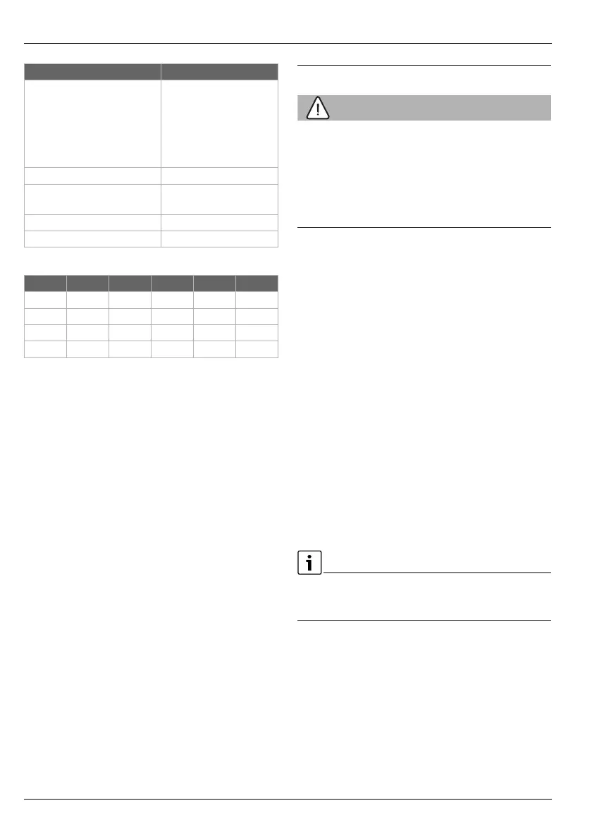
Table 7 Electrical resistances of the supplied swimming pool
temperature sensor
2.3 Cleaning and care
▶ Wipe the casing with a damp cloth when necessary.
Never use aggressive or caustic cleaning agents for this.
2.4 Additional accessories
For detailed information about suitable accessories, refer to
the catalogue or Internet page of the manufacturer.
• For a mixed swimming pool circuit:
– Mixing valve motor; connection to VC1 (follow the
technical documentation of the installed heat pump for
the correct positioning of the mixer)
– Swimming pool temperature sensor; connection to
TC1.
Installation of additional accessories
▶ Install the additional accessories in accordance with legal
regulations and the instructions supplied.
3 Installation
WARNING:
Danger to life from electric shock!
Touching live electrical parts can cause an electric shock.
▶ Before installing this product: Disconnect the heat source
and all other BUS nodes from the mains voltage across all
poles.
▶ Before commissioning: Mount the cover ( Fig. 14 at end
of document).
3.1 Installation
▶ Install the module on a wall as shown at the end of the
document ( Fig. 3 to Fig. 5), or on a mounting rail
( Fig. 6).
▶ Remove the module from the mounting rail
( Fig. 7 at end of document).
▶ Install the swimming pool temperature sensor TC1
( Fig. 1 [3] at the end of the document) in a suitable
location ( Fig. 16 at the end of the document).
3.2 Electrical connection
▶ Observe electrical regulations and use at least cable
H05 VV-...
3.2.1 Establishing the BUS connection and temperature
sensor (extra-low voltage side)
▶ If the conductor cross-sections vary, use a junction box to
connect the BUS nodes.
▶ Switch BUS nodes [B] as shown at the end of the document
via electrical distribution box [A] in star ( Fig. 12) or via
BUS nodes with 2 BUS connections in series ( Fig. 16).
If the maximum total length of the BUS connections between all
BUS nodes is exceeded or the BUS system has a ring structure,
commissioning of the system is not possible.
IP rating
• For installation in heat
source
• For wall-mounted
installation
• Is determined by the IP
rating of the heat
source
•IP 44
Protection class I
ID no. Data plate ( Fig. 15 at
the end of document)
Temperature of ball thrust test 75 °C
Degree of pollution 2
°C °C °C
20 14772 44 5730 68 2488
26 11500 50 4608 74 2053
32 9043 56 3723 80 1704
38 7174 62 3032 86 1420
Technical Data