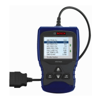
8
|
Operating instructions
|
OBD 1110
|
en
|
OBD 1110
|
Operating instructions | 9
en
577383 REV A | 10.2015 Bosch Automotive Service Solutions 577383 REV A | 10.2015Bosch Automotive Service Solutions
Since DTCs Cleared - shows
status of the monitors since
the DTCs were last erased.
This Drive Cycle - shows
status of monitors since the
start of the current drive
cycle. Refer to the vehicle
service manual for more
detailed information on
emission-related monitors
and their status.
9 Some vehicles do not sup-
port This Drive Cycle. If
vehicle supports both types
of monitors the I / M Monitors
Menu displays.
View Freeze Data
Displays a snapshot of operat-
ing conditions at the time the
Diagnostic Trouble Code was
created. See PID Definitions for
more information.
VIN
The VIN function allows the
tool to request the vehicle’s
VIN number.
The VIN function applies to
model year 2000 and newer OBD
II compliant vehicles.
System Setup
System Setup allows:
• Display contrast to
be changed
• Tool information to be viewed
• Display to be checked
• Operation of the keypad to
be checked
• Memory of the Tool to
be checked
• Units of measure to
be changed
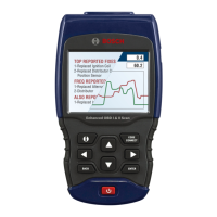
View Data
The View Data function allows
real time viewing of the vehicle’s
computer module’s PID data.
As the computer monitors the
vehicle, information is simultane-
ously transmitted to the Tool.
View Data allows the following
items to be viewed on the Tool:
Sensor data
Operation of switches
Operation of solenoids
Operation of relays
Multiple PIDs may be sent if vehi-
cle is equipped with more than
one computer module (for exam-
ple a powertrain control mod-
ule [PCM] and a transmission
control module [TCM]. The Tool
identifies them by their iden-
tification names (ID) assigned
by manufacturer (i.e. $10 or
$1A). See PID Definitions for
more information.
• MIL ON indicates that the
Malfunction Indicator Lamp
should be ON.
• MIL OFF indicates that the
Malfunction Indicator Lamp
should be OFF.
I / M Monitors (Emissions)
Inspection / Maintenance
Monitors provide a snapshot
of the Emission System opera-
tions by indicating that the
I / M Monitors are Ready or Not
Ready. For an I / M Monitor to
be Ready, the vehicle must have
completed a drive cycle (been
driven long enough under proper
conditions to have completed a
drive cycle). A Monitor must be
listed as Ready to pass an emis-
sions test. If an I / M Monitor is
Not Ready, it is because a drive
cycle has not completed.
The Tool will indicate Ready
(ok), Not Ready (inc), or Not
Applicable (n/a) for each I / M
Monitor. The Tool supports the
following I / M Monitors:
Monitor Expanded Name
Misfire Monitor Misfire Monitor
Fuel System Mon Fuel System Monitor
Comp Component
Comprehensive Compo
-
nents Monitor
Catalyst Mon Catalyst Monitor
Htd Catalyst Heated Catalyst Monitor
Evap System Mon
Evaporative System Mon
-
itor
Sec Air System
Secondary Air System
Monitor
A/C Refrig Mon
Air Conditioning Refriger
-
ant Monitor
Oxygen Sens Mon Oxygen Sensor Monitor
Oxygen Sens Htr
Oxygen Sensor Heater
Monitor
EGR/VVT Sys Mon
Exhaust Gas Recircula
-
tion or Variable Valve Tim-
ing Monitor
NMHC Cat Mon
Non-Methane Hydrocar
-
bon Catalyst
NOX Treat Mon Nitrogen Oxide Treatment
Boost Pres Mon Boost Pressure Monitor
Exhst Gas Sensr Exhaust Gas Sensor
PM Filter Mon Particulate Matter Filter
This is a complete list of I / M
Monitors supported by the Tool.
The number of Monitors read
by the Tool from your vehicle
may vary. A diesel vehicle, for
example, does not have an
Oxygen Sensor Monitor. As a
result, there will be no Oxygen
Sensor Monitor status for a die-
sel vehicle.
Two types of I / M Monitors
tests are: