EasyManua.ls Logo

Bosch Plena LBB1930/20 - External Connection Options; Back-up Power Supply Connection; Line Input and Loop-Through

Bosch Plena LBB1930/20
26 pages
To Next Page IconTo Next Page
To Previous Page IconTo Previous Page
Loading...
External connections
Connect the back-up power supply
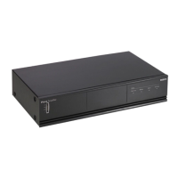
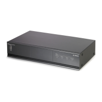
The power amplifier has a 24VDC input (8) screw terminal to connect a back-up power supply.
You must connect an earth (9) to the unit to increase the electrical stability of the system.
1
00V 0 10
0V 0
Prio
rity C
ont
ro
l
led O
u
tp
ut
24 V
D
C
In
Appara
tus
delivered
connectored f
or 230V
~
M
ain P
ower
B
atter
yt
ela
y
s' O
utput
NC
Of
f
O
n
NO
C
OM
NC
NO
C
O
M
NC
1
0
0V
0
7
0V
0
8
ohm
1
00V/7
0V
S
el
ection
(12A
)
Priori
t
y
O
nl
y
0
0
N
o
P
r
ior
i
t
y
P
riority
0
7F
1
F
2
0
7
Batter
y
Pow
e
r
Detection
23
0V~
240
V~
Rated inpu
t
Power : 160 0VA
100 V
70V
0 0
8
Dire c
t O
utp ut
Figure 6.1: Back‑up power supply
Connecting line input and loop-through
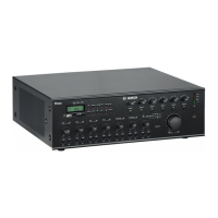
The power amplifier has a balanced line input for connection to a pre‑amplifier or a mixer. Use
the loop‑through connection to connect the power amplifier to another power amplifier if
more power is needed. Each power amplifier must be connected to its own set of
loudspeakers. Do not connect power outputs to each other.
Use program line input 2 (4) and line loop‑through 2 (6) for normal operation without priority.
100V
0 1
0
0V 0
P
r
i
or
i
t
y
Cont
rol
l
ed O
u
tpu
t
Off
O
n
2
4
V
D
C
In
Appar
at
us d
e
l
iv
e
re
d
c
onne
c
t
or
ed
f
or
23
0V~
Main Po
w
er
Batt
e
ry
In
pu
t
F
au
l
t
Relay
s
'
O
u
t
p
u
t
NO
C
O
MN
C
Off
O
n
N
OC
O
M
NC
NO
C
OM N
C
In
p
u
t1Pri orit
y
L
oo
pthro
u
g
h
1
In
p
u
t
2
P
r
ogram
L
oop
thr
ou
g
h
2
I
nput1
P
r
ior
i
ty
2..
.
2
4
V-
I
np
u
t
1
0
V
-
I
np
u
t
2
Input
2
Ena
b
le
2..
2
4V
-
Ena
b
le
0
V
-
Mu
t
e
1
0
0V
0
S
la
ve
I
nput1
00V
+
+
-
-
100V
0
70
V
0
8
o
hm
1
0
0
V/7
0
V
Se
lect
ion(
1
2
A)
P
r
i
or
ity
O
n
ly
0
0
N
o
P
riority
P
rio
r
i
ty
F
7
0
1
F
7
0
2
Ba
tter
y
Powe
r
D
ete
c
tion
Pilo
t-tone
De
tector
2
3
0
V~
2
4
0V~
D
e
si
g
n
&
Q
u
al
i
t
y
T
h
e e
r
a
n
LBB
1
9
3
8
/
1
N
L
-
4
8
2
7H
G
-
10
Pl
e
wer
Amp
l
ifie
r
Ma
x
.
ou
t
putpowe
r
7
20W
R
a
te
d
u
t
p
t ow r 18
0
W
2
30
V
~
,
5
0/
A
03
54
13
Mad
ein
N
6
R
ate
dinp
u
t
Powe
r
:
16
00V
A
I
n
pu
t
1
P
r
iori
t
y
S
la
v
e
I
nput
1
00V
I
np
u
t 2
E
n
abl
e
1
0
0
V 0
100
V
7
0
V0
0
8
Di
r
e
ct
O
u
t
pu
t
In
p
u
t
I
n
p
u
t
I
nput
2
-P ro
gr
amInp ut1
-P r
iori
t
y
2
.
.24 V
De
fa
ul
t O
f
f
G
N
D
2.
.
2
4V
D
e
f
a
ult
On
G
ND
100
V
0 1 0
0V 0
P
r
i
o
r
it
y
C
ontrol
l
e
d Output
O
ff
O
n
24
V
D
C In
App
a
ra
t
us
de
li
v
e
r
e
d
c
onn
e
c
t
or
ed
f
or2 30V
~
M
a
inP
o
w
er
B
a
ttery
I
n
pu
t
F
a
u
l
t Re
l
ay
s'
Out
p
ut
N
O
C
O
MNC
Off
O
n
N
O
CO
M
N
C
NO CO
M
N
C
In
p
ut
1
P
rior
i
ty
Loo
pt
h
roug
h
1
Input
2
P
r
o
g
r
a
m
L
o
o
pthr
o
u
g
h2
I
np
ut1
P
r
ior
i
t
y
2
.
.
.
2
4
V-Inp
u
t
1
0
V
-Input
2
Input
2Enab
le
2
.
.
2
4
V
-
Ena
b
l
e
0V
-
M
u
te
1
0
0V
0
Sl
a
ve
I
n
p
u
t
100
V
+
+
-
-
1
0
0
V
0
7
0
V
0
8o
h
m
1
0
0
V
/7
0
V
S
ele
c
ti
o
n
(
1
2
A)
Priorit
y
O
nly
0
0
No
P
r
i
or
i
ty
P
ri
ority
F
7
0
1
F
7
0
2
B
a
t
t
er
y
P
o
w
e
r
Detection
P
i
lo
t
-to
ne
De
te
ctor
230V~
2
4
0
V
~
D
es
i
g
n
&
Qu
a
l
it
y
T
h
e
Net
h
e
r
l
a
n
d
s
L
B
B 19
3
8
/10
N
L
-
4
827H
G
-
10
Pl
e
n
a4
8
0WPower
Am
p
l
i
fie
r
Ma
x
.output
p
ower
7
20W
R
at
e
do
utputpo
w
e
r
1
8
0W
230V~,
50/
6
0
Hz
S/N.
8
9
0
0
1
9
3
8
1
0
0
1
A
0
3
5413
M
a
d
e
i
n
C
hin
a
N
6
63
Rated
i
nput
P
ower
:
16
00V
A
I
np
u
t 1
P
r
i
or
i
t
y
S
l
a
v
e
I
n
p
ut
100 V
I
n
p
u
t
2
E na
ble
100 V 0
100 V
70
V0 0
8
D
ire ct O
utpu
t
I
npu
t
I
nput
I
npu
t
2
-P
r
ogr
am
I
n
put 1
-P r
io
r
i
t
y
2..
24V
Def
a
ult Off
G
ND
2.. 24
V
D
efau l
t
O
n
G
N
D
1
15
V
- 230V
-
I
n
+2
4V-
+
24V
-
R
a
t
edinput
Power :5 0VA
T1
.
0
AL
250V
A
ppa
ratus deli
v
er
e
d
conne
cted for230V -
T
h
i
s apparatus m
u
s
t
be
e
arthed
W
ar
n
i
ng
MasterO ut
1-
4
3
5
T
r
igger 1
Tel
/EM
G
0
Ou
t
C
all In
C
a
l
l
A
ctiv
e
Zone
6
Zone 5
Zone 1
C
D
L
R
Tri
g
g
er 2
PC
A
ud
i
oIn
1.Audio+
2.0V
3.Aud
io
-
4.24V d.c
.
5.A
l
lcal
l
6.Da
ta-
7.Da
t
a+
8.
Chs
.
GND
RS 232
/Li
ne
/L
in
e
Aux
3
5
4
1
2
3
7
6
8
5
4
1
2
2
1
+
-
GND
3
1
2
+
-
GND
3
Zone 2
Zon
e
3
Zon
e
4
DC Out
DC In
100V
100V
0
0
100V
0
100V
0
100V
100V 0
0
100V
100V 0
0
4
6
Figure 6.2: Line input and loop‑through
6
6.1
6.2
12 en | External connections Plena Power Amplifiers
2014.01 | V1.1 | LBB193x/x0 Installation and Operation manual Bosch Security Systems B.V.

Related product manuals