EasyManua.ls Logo

Bosch Plena LBB1930/20 - Operating the Amplifier; Switching On the Amplifier

Bosch Plena LBB1930/20
26 pages
To Next Page IconTo Next Page
To Previous Page IconTo Previous Page
Loading...
Operation
Switch ON
Put the power switch on the rear of the power amplifier in the “I” position.
1
00 V 0
1
0
0V 0
Prio
ri
ty C
o
n
trolled Output
2
4V
D
C
In
Appara
tus deliv
ered
connectored
for 23
0
V~
Main
P
ower
B
attery
t
elays' Output
NC
O
O
n
NO
C
OM
NC
NO
C
O
M
N
C
100V
0
70V
0
8
o
h
m
100V/
7
0V
Se
l
e
ctio
n(12A)
Prio
rity
Only
0
0
No
Prio
ri
ty
P
ri
ority
F701
F702
B atter
y
Power
Det
ecti
o
n
23
0V
~
240
V~
Rated input
Pow 1:re 600 VA
100V
70V
0
0
8
Dire c
t O
utput
100V 0 1 00V 0
PriorityC
on
t
r
o
lledO u
tput
O
O
n
2
4V D
CI
n
A
p
p
ara
tusd
el
ivered
co
nnecto
re
d
fo
r230V ~
Ma
i
nP
ower
B
atter
y
Input
F
au
ltR el
ays' Out
put
NO
C
O
M
NC
O
O
n
NOCO
M
NC
NOC
O
MNC
I
np
ut1Pri
ority
Lo
o
pth
r
ou
gh1
Inp
ut2Pr
ogram
L
o
o
pthroug
h2
Input1Priori
ty
2
.
.
.2
4V-
I
n
p
ut
1
0V-Input2
I
nput
2
Enab
le
2
.
.24V-Enable
0V-Mute
1
00
V
0
Sla
v
e
Inp
ut100V
+
+
-
-
1
0
0
V
0
70V
0
8ohm
100V/
7
0V
Selection
(12A)
P
r
iorit
y
Onl
y
0
0
NoPrio
r
i
ty
Priority
F701
F
70
2
Battery
Power
Dete
cti
o
n
Pilot-tone
Detector
230V~
24
0V~
Desig
n&Qua
lity
T
heNether
l
ands
L
B
B
1
93
8/
10
NL
-4
8
2
7
H
G
-
1
0
Pl
e
n
a
480WPowerAmplifier
M
ax
.o
u
tp
u
tpowe
r
72
0W
R
a
t
edoutp
utp
o
wer180W
230V~,
5
0/60Hz
S/N.
8
90019
381
00
1
A
0
35
413
Mad
e
i
nC
h
i
na
N66
3
Ra
tedinput
Pow
e
r:
1
6
0
0
V
A
Input 1
Pr
iori
t
y
Sla
ve I
nput
1
00
V
Inpu
t2
Ena b
l
e
1
0
0V 0
100V 70V0
0
8
D
irect O
utput
Inp
utInput
I
n
pu
t2
-
Pro gr
a
m
Input 1-P r
ior
ity
2
.
.24
V
Defau
l
t
Of
f
GND
2
..24 V
Defau
l
t
On
GND
Line fuse
T10
L
2
5
0V
Figure 8.1: Power switch and power connection
0 dB
-6 dB
-20 dB
taehrevOyrettaB MainsPilot-Tone
Status
1 2 3 4 5 6
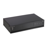
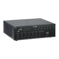
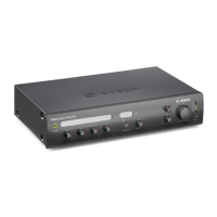
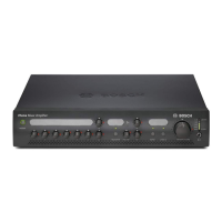
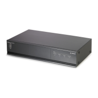
Figure 8.2: LBB 1930/20 LBB 1935/20, LBB 1938/x0
If mains power or back‑up power is available, the VU‑bar (1) on the front of the power
amplifier is lit and shows the output level of the amplifier.
If the internal temperature reaches a critical limit due to poor ventilation or overload, an
overheat protection circuit switches “OFF” the power stage. The overheat indicator (5) shows
on the front panel and the Input fault relay switches over if the power stage is switched “OFF”
by the overheat protection circuit. The Battery operation indicator (3) lights up if the mains
power supply is failing and the back‑up battery is in use.
8
8.1
Plena Power Amplifiers Operation | en 17
Bosch Security Systems B.V. Installation and Operation manual 2014.01 | V1.1 | LBB193x/x0

Related product manuals