Bosch Security Systems | 2006-11 | 9922 141 50751en
Plena Power Amplifier | Installation and User Instructions | Amplifiers en | 12
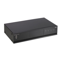
3.4 Installation
The power amplifier is suitable for table-top and 19-inch
rack-mounting installation. Two brackets for rack-
mounting are supplied. See figure 3.5 for installation
details.
The power amplifier has an internal fan regulated to
keep the temperature inside the unit within the safe
operating condition.
3.5 External connections
3.5.1 Connect the back-up power
supply
The power amplifier has a 24 Vdc input (8) screw
terminal to connect a back-up power supply. You must
connect an earth (9) to the unit to increase the electrical
stability of the system.
figure 3.5: Brackets for rack-mounting
0dB
-6 dB
-20 dB
Plena Booster Amplifier
figure 3.6: Back-up power supply
1
0
0V 0 10
0V 0
Priority C
ontrolled Output
24V DC
In
Apparatus delivered
connectored for 23
0V~
Main P
ower
B
atter
y
t
elays' Output
NC
Off O
n
NO
C
OM
NC
NO
C
O
M
NC
10
0V
0
70
V
0
8ohm
10
0V/70V
Sele
ction
(12
A)
Prio
rity
Only
0
0
No
Prio
rity
Pri
o
rity
F701
F702
Batter
y
Power
Detection
23
0V~
240V~
Ratedinput
Power : 1600VA
100V
70V
00
8
Direc
tO
utput
1
00V 0 1
0
0V 0
Priori
tyC
on
trol
ledOutput
Off
O
n
24
VDC
In
A
p
paratusd
elivered
co
nn
e
cto
re
dfor23
0V~
Mai
nP
owe
r
B
atter
y
I
n
put
FaultRelays' Output
NO
C
O
M
NC
Off O
n
NO
C
O
M
NC
NOC
O
M
NC
Input
1
Pr
i
o
rit
y
Lo
o
pthr
o
ug
h
1
I
np
ut
2
P
ro
g
ra
m
Lo
o
pthr
o
ug
h2
Inp
ut
1
P
rior
i
ty
2..
.2
4
V
-
Inp
ut
1
0V-
Inp
ut
2
I
np
ut
2
En
able
2.
.
2
4V
-
Enab
le
0
V-Mute
1
00
V
0
S
l
a
ve
I
np
ut1
0
0
V
+
+
-
-
1
0
0
V
0
7
0
V
0
8
o
hm
1
0
0
V/
7
0
V
Se
l
e
ct
i
o
n
(
1
2
A
)
Pr
io
r
i
t
y
O
n
l
y
0
0
N
o
Pr
io
r
it
y
P
r
io
r
i
t
y
F
7
0
1
F
7
0
2
Batte
ry
Power
Detection
Pilot
-ton
e
Detector
230V~
24
0V~
Des
i
g
n
&
Qua
l
i
ty
T
heNet
he
r
l
a
n
d
s
LB
B
1
9
3
8
/1
0
N
L
-
48
2
7
H
G
-
1
0
P
l
e
n
a
4
8
0W
PowerA
m
pl
i
fi
e
r
Ma
x
.
o
u
tp
u
tp
o
we
r72
0W
Ra
te
doutp
u
t
po
we
r18
0W
23
0V~,
5
0/
60Hz
S/
N.
89
0
0
1
93
8
1
00
1
A
0
3
54
1
3
M
a
de
i
n
C
h
i
n
a
N6
63
R
ate
din
pu
t
Pow
er: 1
6
00V
A
Input 1
Pr
ior
ity
S
la
veIn put
100V
Inpu
t2
Enab
le
10
0V
0
100V 70 V0
0
8
Direc
tO
utput
InputInput
Inpu
t2-P
rogr
amInpu
t1
-Pr
ior
ity
2
..2
4
V
Defa
ult Of
f
GN
D
2..24
V
Defa
u
ltO n
GN
D
12 VDC
12 VDC
- + - +
9
8
 Loading...
