Bosch Security Systems | 2006-11 | 9922 141 50751en
Plena Power Amplifier | Installation and User Instructions | Operation en | 19
5Operation
5.1 ON and OFF
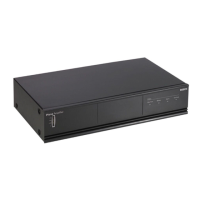
5.1.1 Switch on
Put the power switch on the rear of the power amplifier
(see figure 5.1) in the I position.
If mains power or back-up power is available, the
VU-bar (1) on the front of the power amplifier is lit and
shows the output level of the amplifier (see figure 5.2).
If the internal temperature reaches a critical limit due to
poor ventilation or overload, an overheat protection
circuit switches OFF the power stage. The Overheat
indicator (5) shows on the front panel and a signal is
given on the Input fault relay if the power stage is
switched OFF by the overheat protection circuit.
The Battery operation indicator (3) lights up if the mains
power supply is failing and the back-up battery is in use.
5.1.2 Switch off
Put the power switch of the power amplifier (see figure
5.1) in the O position.
figure 5.1: Power switch
1
00V 0 1
0
0V 0
Priority C
ontrolled Output
24V DC
In
Apparatus delivered
connectored for23
0V~
Main P
ower
Battery
t
elays' Output
NC
Off O
n
NO
C
OM
NC
NO
C
O
M
NC
100V
0
70V
0
8ohm
100V/70V
Sel
ection (12A)
Priority
Onl
y
0
0
No
Priori
ty
Pri
ori
ty
F7
01
F7
02
Batter
y
Power
Detection
23
0V~
240V~
Rated input
Power : 1600VA
100V
70V
0 0
8
Direc
tO
utput
100V 0 1 0
0V 0
PriorityC
on
tro
l
ledOutput
Off
O
n
24
VDC
In
App
ar
atus
delive
r
ed
co
nn
ec
tor
e
dfor 23
0V~
MainP
owe
r
B
a
tter
y
I
n
p
ut
FaultR
elays'Out
put
NO
C
OM
NC
Off
O
n
NO
C
O
M
NC
NOC
O
M
NC
I
n
pu
t
1Pri
or
i
t
y
L
o
o
pthr
ou
gh
1
I
np
ut
2
P
ro
g
r
a
m
L
o
o
pt
hr
ou
gh
2
I
np
ut
1
Pri
o
r
i
ty
2
..
.2
4
V
-
Inp
ut
1
0
V-
In
p
ut2
In
p
ut
2
En
able
2..
2
4V
-
Enable
0V-
Mut
e
100V
0
S
l
a
ve
In
p
ut
1
00V
+
+
-
-
1
0
0
V
0
7
0
V
0
8
o
hm
1
0
0
V/
7
0
V
Se
l
e
ct
i
o
n
(
1
2
A
)
Pr
io
r
i
t
yOn
l
y
0
0
N
o
Pr
i
o
r
i
t
y
Pr
i
o
r
i
t
y
F
7
0
1
F
7
0
2
Battery
Power
Detectio
n
Pilot
-ton
e
Detector
230V~
24
0V~
Desi
g
n
&
Qua
l
it
y
T
he
N
et
herl
a
nd
s
LBB
1
9
3
8
/
10
N
L
-
482
7
H
G
-
1
0
P
l
e
n
a
4
8
0W
P
o
werA
m
pl
i
fi
e
r
Ma
x
.
o
u
tp
u
tp
o
we
r7
2
0W
R
a
t
e
dout
p
u
t
po
we
r180W
23
0V
~,
5
0
/
6
0Hz
S/
N.
89
0
0
1
9
3
81
00
1
A
0
3
5
4
1
3
M
a
de
i
n
C
h
i
n
a
N
6
6
3
R
ated
in
pu
t
Pow
e
r: 1
6
0
0
V
A
Inpu
t1
P
r
ior
ity
Sla
ve I
nput
100V
Inpu
t2
E
nab
le
10
0V
0
100V 70V0
0
8
Dire c
tO
utput
InputInput
Inpu
t2-Prog r
am
Inpu
t1
-P
r
ior
ity
2
..24
V
Defa
u
ltO f
f
GN
D
2..2 4
V
De
fa
ul
tO n
GND
Linefuse
T10L250V
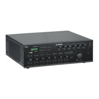
figure 5.2: Front panel LBB1938/20
0dB
-6 dB
-20 dB
Battery OverheatMainsPilot-Tone
Status
Plena Booster Amplifier
1
3 4 52 6
 Loading...