EasyManua.ls Logo

Bosch Plena Power Amplifier - Operation and Technical Data; Powering the Amplifier On and Off

Bosch Plena Power Amplifier
24 pages
To Next Page IconTo Next Page
To Previous Page IconTo Previous Page
Loading...
Bosch Security Systems | 2006-11 | 9922 141 50751en
Plena Power Amplifier | Installation and User Instructions | Operation en | 19
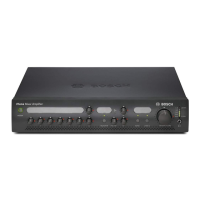
5Operation
5.1 ON and OFF
5.1.1 Switch on
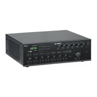
Put the power switch on the rear of the power amplifier
(see figure 5.1) in the I position.
If mains power or back-up power is available, the
VU-bar (1) on the front of the power amplifier is lit and
shows the output level of the amplifier (see figure 5.2).
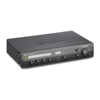
If the internal temperature reaches a critical limit due to
poor ventilation or overload, an overheat protection
circuit switches OFF the power stage. The Overheat
indicator (5) shows on the front panel and a signal is
given on the Input fault relay if the power stage is
switched OFF by the overheat protection circuit.
The Battery operation indicator (3) lights up if the mains
power supply is failing and the back-up battery is in use.
5.1.2 Switch off
Put the power switch of the power amplifier (see figure
5.1) in the O position.
figure 5.1: Power switch
1
0
0
V
0
1
0
0V 0
Pri
o
r
ity
C
o
n
trolled
Outpu
t
2
4
V
D
C
I
n
Appara
tus deliv
ere
d
connectored
for23
0
V~
Main P
ower
B
attery
t
elays'
Outpu
t
N
C
Off
O
n
N
O
C
O
M
N
C
N
O
C
O
M
N
C
1
00
V
0
7
0V
0
8o
h
m
100
V
/
7
0
V
S
e
l
e
c
t
i
o
n
(
1
2
A)
Pr
i
o
r
it
y
On
l
y
0
0
N
o
P
r
i
o
ri
t
y
P
ri
o
ri
t
y
F
7
0
1
F
7
0
2
B
atter
y
P
o
wer
Det
ectio
n
23
0V
~
24
0
V~
Rated input
P
ow
er : 1
6
00VA
100V
70V
0
0
8
Direc
tO
utput
10
0
V
0
1
0
0
V
0
P
r
i
o
ri
t
y
C
o
n
t
r
o
l
l
e
d
O
u
t
put
O
f
f
O
n
2
4
VD
C
I
n
A
p
p
a
r
a
t
u
s
d
e
l
i
ve
r
e
d
c
o
n
n
e
c
t
o
r
e
d
fo
r
2
3
0
V
~
Ma
i
n
P
o
w
e
r
B
a
t
t
e
r
y
I
n
p
u
t
F
au
l
tR
e
l
ays'
O
u
t
put
N
O
C
OM
NC
O
ff
O
n
N
O
C
O
M
N
C
NO
C
O
M
NC
I
n
p
u
t
1
P
r
i
o
r
i
t
y
L
o
o
p
t
hr
ou
gh
1
I
n
p
u
t
2
P
r
o
g
r
a
m
L
o
o
p
t
hr
o
u
g
h
2
I
n
p
u
t
1
P
r
i
o
r
i
ty
2
.
.
.
2
4
V
-
I
n
p
u
t
1
0
V-
I
n
p
u
t
2
I
n
p
u
t
2
E
n
a
b
l
e
2
.
.
2
4
V
-
E
n
ab
l
e
0
V
-
M
u
t
e
1
0
0
V
0
S
l
a
v
e
I
n
p
u
t
1
0
0
V
+
+
-
-
1
0
0
V
0
7
0
V
0
8
o
hm
1
0
0
V/
7
0
V
S
e
l
e
ct
i
o
n
(
1
2
A
)
P
r
i
o
r
i
t
yO
n
l
y
0
0
N
o
P
r
i
o
r
i
t
y
P
r
i
o
r
i
t
y
F
7
0
1
F
7
0
2
B
a
t
t
e
r
y
P
o
w
e
r
D
et
e
ct
i
o
n
P
i
lot
-
t
o
n
e
D
et
e
ct
or
2
3
0
V~
2
4
0
V~
D
e
s
i
g
n
&
Q
u
a
l
i
t
y
T
he
N
et
herl
a
n
d
s
L
B
B
1
9
3
8
/
1
0
N
L
-
4
82
7
H
G
-
1
0
P
l
e
n
a
4
8
0W
P
o
w
e
rA
m
pl
i
f
i
e
r
Ma
x
.
o
u
t
p
u
tp
o
w
e
r7
2
0W
R
a
t
e
do
ut
p
u
t
p
o
w
e
r1
80W
23
0
V
~
,
5
0
/
6
0
Hz
S
/
N
.
8
9
0
0
1
9
3
8
1
0
0
1
A
0
3
5
4
1
3
M
a
d
e
i
n
C
h
i
n
a
N
6
6
3
R
a
t
e
d
i
n
pu
t
P
o
w
e
r
:
1
6
0
0
V
A
In
p
u
t1
P
r
i
o
r
i
t
y
S
l
a
v
e
I
np
u
t
1
0
0
V
In
p
u
t2
E
n
ab
l
e
1
0
0
V
0
1
0
0
V
7
0
V0
0
8
D
i
r
e
c
tO
u
t
p
ut
I
n
p
ut
I
n
p
ut
I
n
p
u
t2
-
P
r
o
g
r
a
m
I
n
p
u
t
1
-
P
r
io
r
it
y
2
.
.
2
4
V
D
e
fa
u
l
t
O
f
f
G
N
D
2
.
.
2
4
V
D
e
f
a
u
l
t
O
n
G
N
D
L
i
n
ef
u
s
e
T10
L
2
5
0
V
figure 5.2: Front panel LBB1938/20
0dB
-6 dB
-20 dB
Battery OverheatMainsPilot-Tone
Status
Plena Booster Amplifier
1
3 4 52 6

Related product manuals