English - 4
Speed Table
The values shown in the chart are standard val-
ues. The necessary speed depends on the mate-
rial and the operating conditions, and can be de-
termined by practical testing.
Constant Electronic Control
(POF 1300 ACE)
Constant electronic control holds the speed con-
stant at no-load and under load, and ensures uni-
form working performance.
Depending on the cutting operation, the depth-of-
cut can be preset in several steps.
The adjustment of the depth-of-cut may
only be carried out when the router is
switched off.
Coarse Adjustment of the Depth-of-cut
– Place the router on the workpiece to be ma-
chined.
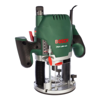
POF 1300 ACE: Set the fine adjustment for
depth-of-cut in the center position with fine-ad-
justment knob 1; to do this, turn the fine-adjust-
ment knob until the markings 24 on the backside
of the router are in alignment, as shown.
Afterwards turn scale 2 to “0” (see figure ).
Set step buffer 11 to the lowest position; the
buffer snaps-in noticeably.
POF 1100 AE: Set the screws for the step
buffer 21 halfway in or out.
Set step buffer 11 to the lowest position; the
buffer snaps-in noticeably. When fine adjustment
of the depth-of-cut is desired, select one of the
3 steps that is fitted with the screw 21.
POF 1100 AE/POF 1300 ACE:
– Loosen locking screw 8, so that depth stop 6
can be moved freely.
– Release the clamping lever 3 by turning in
clockwise direction and slowly lower the router
until the router bit touches the surface of the
workpiece. Lock the router in position by turn-
ing the clamping lever 3 in anticlockwise direc-
tion.
– Press depth stop 6 downwards until it touches
the stop buffer 11. Press down slider 7 and set
to “0”.
– Adjust the depth stop 6 to the required routing
depth and tighten the wing screw 8. It is impor-
tant that the slider 7 is not adjusted afterwards.
– Release the clamping lever 3 and guide the
router back up again.
The coarse adjustment of the depth-of-cut should
be checked by a trial cut and corrected, if neces-
sary.
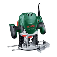
Fine Adjustment of the Depth-of-cut
(POF 1300 ACE)
After a trial cut, fine adjustment can be carried out
by turning the fine adjustment knob 1 (1 scale
mark = 0.1 mm/1 rotation = 2.0 mm). The max-
imum adjustment is approx. +/– 8 mm.
Example: Slide router upwards again and meas-
ure the depth-of-cut (set value = 10.0 mm; actual
value = 9.8 mm).
– Lift up router and underlay guide plate 13 in
such a manner that the router can plunge
freely without the router bit touching the work-
piece.
Lower the router again until the depth stop 6
touches the step buffer 11.
– Afterwards set scale 2 to “0”.
– Loosen wing screw 8.
– With the fine adjustment 1, advance the depth-
of-cut in clockwise direction by 0.2 mm/
2 scale marks (= difference between required
value and actual value).
– Retighten wing screw 8 again.
– Slide router upwards again and check depth-
of-cut by carrying out another trial cut.
After setting the depth-of-cut, the position of the
index mark 7 on the depth stop should not be
changed anymore so that the currently adjusted
setting can always be read off of scale 5.
Material Router bit-Ø Speed stages
Hardwood 4 – 10 mm 5–6
(Beech) 12 – 20 mm 3–4
22 – 40 mm 1–2
Softwood 4 – 10 mm 5–6
(Pine) 12 – 20 mm 3–6
22 – 40 mm 1–3
Particle board 4 – 10 mm 3–6
12 – 20 mm 2–4
22 – 40 mm 1–3
Plastic 4 – 15 mm 2–3
16 – 40 mm 1–2
Aluminium 4 – 15 mm 1–2
16 – 40 mm 1
Setting the Depth-of-cut
C
1 609 929 F23 - Buch Seite 4 Montag, 19. April 2004 8:27 08
16 • 1 609 929 F23 • 04.04
 Loading...