English | 9
Bosch Power Tools 1 609 92A 1V7 | (6.9.16)
Symbols
The following symbols can be important for the operation of
your power tool. Please memorise the symbols and their
meanings. The correct interpretation of the symbols helps
you operate the power tool better and more secure.
Product Description and Specifica-
tions
Read all safety warnings and all instruc-
tions. Failure to follow the warnings and in-
structions may result in electric shock, fire
and/or serious injury.
Intended Use
The machine is intended for stationary use with cutting discs
to perform lengthways and crossways straight cuts or mitre
cuts to 45° in metal materials without the use of water.
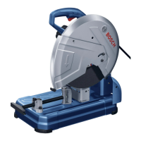
Product Features
The numbering of the components shown refers to the repre-
sentation of the power tool on the graphic pages.
1 Lock-on button for On/Off switch
2 On/Off switch
3 Handle
4 Retracting blade guard
5 Spindle lock
6 Cutting disc
7 Angle stop
8 Clamping spindle
9 Quick-release button
10 Spindle handle
11 Mounting holes
12 Hex key (8 mm)
13 Base plate
14 Locking screw for angle stop
15 Transport safety-lock
16 Tool arm
17 Transport handle
18 Blade guard
19 Spark guard
20 Tool spindle
21 Clamping flange
22 Washer
23 Hexagon bolt
Accessories shown or described are not part of the standard deliv-
ery scope of the product. A complete overview of accessories can
be found in our accessories program.
Technical Data
Assembly
Avoid unintentional starting of the machine. During as-
sembly and for all work on the machine, the power plug
must not be connected to the mains supply.
Delivery Scope
Carefully remove all parts included in the delivery from their
packaging.
Remove all packaging material from the machine and the ac-
cessories provided.
Before starting the operation of the machine for the first time,
check if all parts listed below have been supplied:
– Cut-off grinder with mounted cutting disc
–Hex key 12
Symbol Meaning
Keep hands away from the cutting ar-
ea while the machine is running. Dan-
ger of injury when coming into contact
with the cutting disc.
Wear ear protectors. Exposure to
noise can cause hearing loss.
Wear safety goggles.
Wear a dust respirator.
Wear protective gloves.
Cut-off grinder GCO 14-24
Article number
3 601 M37 1..
Rated power input
W 2400
No-load speed
min
-1
3800
Weight according to
EPTA-Procedure 01/2003 kg 17
Protection class
/II
Permissible workpiece dimensions (maximum/minimum) see page 11.
The values given are valid for a nominal voltage [U] of 230 V. For differ-
ent voltages and models for specific countries, these values can vary.
Dimensions of suitable cutting discs
Cutting disc diameter, max.
mm 355
Cutting discs width, max.
mm 3
Mounting hole diameter
mm 25.4
OBJ_BUCH-1307-005.book Page 9 Tuesday, September 6, 2016 4:19 PM
 Loading...