22/48 Safety instructions
Bosch Rexroth AG, 4WRPD(H), 4WRPQ(H), 4WRPF(H), 4WRLD, 4WRLF, 4WRLQ, 5WRPF10, 5WRPQ10; RE 29391-B/05.2021
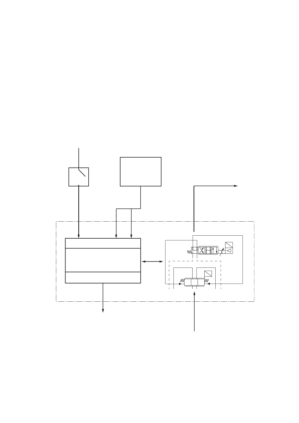
2.7.11 Connection example/block diagram for pilot-operated valves (pilot valve
with one solenoid)
For type III according to EN 201:2009, two separate switch-off paths are required.
The following overview illustrates a realization example of a switch-off path for an
injection molding machine with pilot operated valve (pilot valve with one solenoid)
on Multi-Ethernet basis. For the second switch-off path, an additional suitable
valve is required. For this application, the specific requirements of EN 201:2009
are to be complied with.
The connection example only shows the safety-relevant signals of the Multi-
Ethernet electronics. For all other signals and interfaces, refer to the valve-specific
data sheets.
Fig. 3: Block circuit diagram for pilot operated valves (pilot valve with one solenoid)
A B
P T
b
G
U
a
a0b
AB
PT
G
U
A B
(1236) = 8+4
(ABCD) = 6+PE
1, 2, 3, 8
are safety-related connections of the
11+PE connector of the valve on Multi-Ethernet
basis; for further connections, see valve data
sheet (values in brackets: connections when
using a 8+4 connector and when using a 6+PE
connector)
Hydraulics
actuator side
PELV/SELV
24 V mains
adaptor according
to VDE0100
part 410
Enable signal
that can be
switched off
safely
Inputs
Multi-Ethernet
electronics
Outputs
GND
24 V
(18...36 V)
Enable
1(1)(A)
Enable
acknowledgement
Hydraulics supply
side
2(2)(B)
3(3)(D)
8(6)(C)