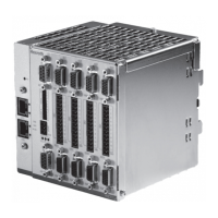
Do you have a question about the Bosch Rexroth VT-HMC 1X Series and is the answer not in the manual?
| Brand | Bosch |
|---|---|
| Model | Rexroth VT-HMC 1X Series |
| Category | Control Unit |
| Language | English |
Defines the scope and applicability of the documentation for the digital axis control VT-HMC series 1X.
Lists necessary and helpful documents for commissioning and operating the product.
Explains symbols, terms, and abbreviations used to ensure clarity and safe operation.
Details the structure and meaning of safety instructions, signal words, and hazard classifications.
Explains non-safety-relevant symbols used to enhance document comprehension.
Lists and defines terms used throughout the documentation for better understanding.
Provides a list of abbreviations used in the documentation along with their meanings.
Introduces the safety chapter and emphasizes the importance of observing safety instructions.
Describes the product's intended application for controlling hydraulic axes and specifies professional use.
Defines prohibited uses and warns against potential risks of using the product incorrectly, especially in safety-relevant applications.
Outlines the necessary expertise and training required for personnel working with the product and related systems.
Provides general safety guidelines, including accident prevention, environmental protection, and product handling.
Covers specific safety measures related to hazardous movements, electrical voltage, and lightning protection.
Advises on checking and wearing appropriate personal protective equipment.
Details the machine end-user's responsibilities regarding IT security concepts for the product.
Covers risks from high voltage, incorrect cables, overloading, short circuits, and temperature extremes.
Lists the items included in the product's delivery package, excluding accessories.
Details the digital axis control's capabilities, including control types and operating modes, and mentions the engineering tool.
Describes the product's design for harsh environments and lists controller variants and operating modes.
Lists comprehensive monitoring functions like undervoltage, communication errors, and short-circuit detection.
Describes the types of measuring systems supported for hydraulic axes, including incremental, absolute, and analog inputs.
Explains the function of the SD memory card slot for saving PLC programs and optional data.
Provides context on interfacing, higher-level controls, and main application fields for the product.
Describes the label on the VT-HMC...1X showing key data like material number, serial number, and date of production.
Provides instructions for preparing the unit for storage, including packaging, temperature, and environmental protection.
Specifies environmental requirements and precautions for installing the VT-HMC...1X, including contamination and orientation.
Lists recommended accessories for connecting the axis control, not included in the scope of delivery.
Details the steps for physically mounting the VT-HMC...1X onto a DIN mounting rail in a control cabinet.
Advises on optimal placement of the VT-HMC...1X to avoid interference and ensure proper cooling, away from direct sunlight.
Provides instructions for connecting the power supply, emphasizing short connections and proper cable configuration.
Explains how to supply external components like encoders and pressure cells using the VT-HMC...1X's outputs.
Details the correct method for shielding signal cables using copper braid and grounding bars for EMC protection.
Offers general guidelines for cable routing, signal line continuity, and wire usage to minimize interference.
Illustrates how to connect wires to terminal blocks, including the use of wire end ferrules and tension spring terminals.
Explains the use of keying elements to prevent incorrect connection of multi-point connectors.
Provides detailed pin assignments for connectors XG20 and XG21, essential for proper wiring.
Shows a practical wiring example for connecting a pressure sensor to an analog input.
Illustrates external power supply for a device/sensor with 4-20mA output.
Shows wiring for a 3-conductor sensor supplied by the VT-HMC...1X with ±10V output.
Illustrates wiring for a 4-conductor sensor supplied by the VT-HMC...1X with ±10V output.
Demonstrates external power supply for a device/sensor with a 4-conductor cable and ±10V output.
Lists common causes of interference and suggests methods for suppression related to other electrical components.
Outlines fundamental principles for commissioning, emphasizing safe handling of connectors and prerequisites for operation.
Lists the system requirements for the operator PC and software needed for commissioning and operation.
Details the procedure to activate the synchronization function using an SD card and the status LED indicators.
Guides users through creating a project, scanning devices, establishing online connection, and creating PLC applications.
Describes the capabilities of IndraWorks software for parameterization, diagnostics, and programming, including download information.
Explains how to use IndraWorks software for diagnostics and how the VT-HMC...1X status LEDs indicate operating states.
Provides instructions for cleaning the device, including precautions against contaminants, humidity, and aggressive cleaning agents.
States that the VT-HMC...1X can only be replaced as a complete unit and prohibits unauthorized modifications.
Outlines the initial steps for safely decommissioning the system before demounting the unit.
Details the procedure for removing the VT-HMC...1X from the DIN rail, including disconnecting cables and releasing the latch.
Guides on how to prepare the unit for storage or subsequent use, emphasizing original packaging and environmental protection.
Advises on the proper disposal of the product and packaging material in accordance with local regulations.
States that the control electronics must not be extended or converted; doing so voids the warranty.
Offers a systematic approach to troubleshooting, emphasizing system overview, fault analysis, and using diagnostic tools.
Refers to the technical data sheet 30239 for detailed specifications of the VT-HMC series 1X.
Provides contact information for service, spare parts, headquarters, and technical support.
Lists third-party software components used by the Hydraulic Drive devices and their respective license terms.

