RE 30239-B, Edition 01.2021, Bosch Rexroth AG
Installation | Digital axis control VT-HMC...1X 19/36
7.3.2 Power supply
▶ Keep the connection as short as possible and install supply and return
conductors (+24 V/GND) together. For voltage, see data sheet 30239.
▶ Install power cables consisting of two individual wires (voltage supply) in
parallel or as twisted cable.
7.3.3 Supply of external components
For the supply of a 24-V encoder, the input voltage of the VT-HMC...1X at XD1 must
meet the requirements of the encoder (e.g.: 24 V±5 %, residual ripple <500 mV).
Analog components such as pressure cells can be supplied via the analog voltage
output V
encoder_ANA
at XG20/XG21.
Prerequisite: The supply of the VT-HMC...1X meets the requirements of the
pressure cell. For further notes on currents, etc., please refer to data sheet 30239.
7.3.4 Shielding
For signal cables, use only cables with a copper braid shield. Connect the cable
shield on one side on a large area using a grounding bar. For this, mount the
grounding bar as close as possible to the VT-HMC...1X and strip the cable sheath
around the cable at the appropriate position. Observe the installation notes given
in the data sheet of the grounding bar (e.g. from Wago: U-shaped busbar, art. no.
790-191, shield clamping saddle, art. no. 790-116).
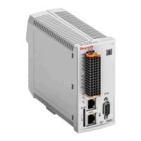
Fig. 2: Shielding of the VT-HMC...1X
 Loading...

