Technical data 97/104
RE 92076-01-B/10.2017, A4... with HS5E pilot control valve/Series 3x, Bosch Rexroth AG
33
90
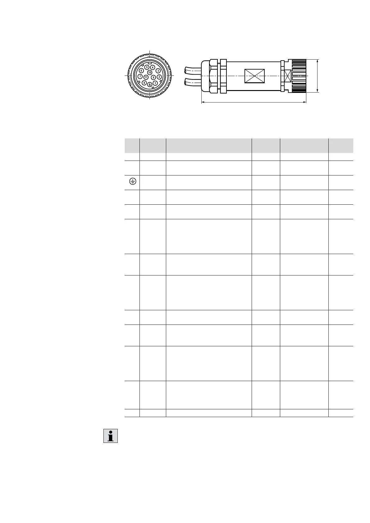
Fig. 31: Pin assignment of the central connector
Table 29: Signals to the central connector
Pin Signal Description Signal
direction
Signal level Code
1 + UB Voltage supply IN +24 V 1
2 L0 Reference potential for voltage
supply
- - 2
Ground Ground connection for the
electronics
- - Yellow/
green
3 DO
Switching output 24 V, max. 1.5 A
Factory setting: Error signal
OUT Logical 24 V
(Load I
max
≤ 50 mA)
White
4 M0 Reference potential for analog
signals
- - Yellow
5 AI 2 Analog input 2 (or digital input,
to be configured by means of
software) Factory setting:
Software command value
standardized
IN Analog +/-10 V or
0-20 mA
(digital 24V)
Green
6 AO 2 Analog output 2 Factory setting:
Software actual value standardized
OUT +/- 10V or
0-20 mA
(Load I
max
≤ 1 mA)
Violet
7 AI 1 Analog input 1 (or digital input,
to be configured by means of
software) Factory setting:
Pressure command value
standardized
IN +/- 10 V or
0-20 mA or
24 V digital
Pink
8 AO 1 Analog output 1 Factory setting:
Actual pressure value standardized
OUT +/- 10V or 0-20 mA
(load I
max
≤ 1 mA)
Red
9 DI Digital input (use can be freely
configured) Factory setting: Error
reset
IN Logical 24 V Brown
10 Actual
pressure
value
High
Actual pressure value input: Signal
level dependent on parameter
setting. Factory setting depending
on option 14 in the ordering code:
0-10 V (V) or disabled (F)
IN 0-10 V,
0-20 mA
(freely
configurable)
Black
11 Actual
pressure
value
Low
Reference potential for actual
pressure value signal (p
actual
High)
- - Blue
n.c. Gray
Connect M0 and L0 in the control cabinet to prevent potential shifts.