50/72 Bosch Rexroth AG EC30X | 3 609 929 728/2014-01
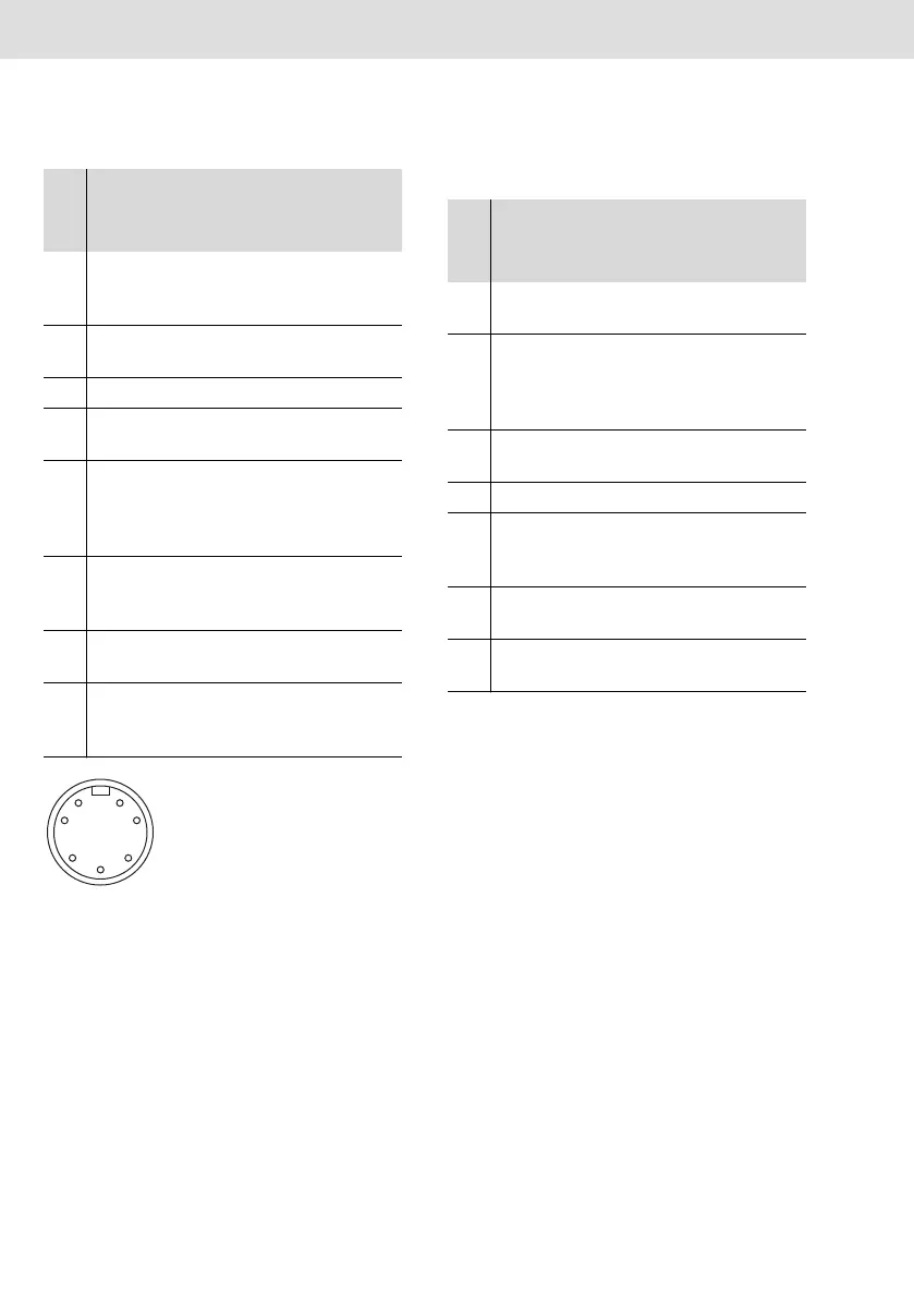
Abb. 2: Servomotor: Connector, 7-pole (fe-
male; view to servomotor)
3 CHB Incremental
transducer
channel 2
12 V
DC
4 GND Reference po-
tential logic
5 INDX Index impulse 12 V
DC
6 VEE 24 V spindle
power supply
24 V
DC
7 MKTF Motor identifi-
cation and mo-
tor tempera-
ture error
12 V
DC
8 HS Release
personnel
safety
24 V
DC
9 CANH Serial spindle
data CAN high
ISO 11 898
10 CHA Incremental
transducer
channel 1
12 V
DC
Tab. 6: Pin assignment of the connector for
spindle connecting line
Pin Signal
Description/
function
Voltage/cur-
rent/stan-
dard
17
2
3
4
5
6
Tab. 7: Pin assignment of the connector for
measurement transducer cable
Pin Signal
Description/
function
Voltage/cur-
rent/stan-
dard
1 VEE 24 V spindle
power supply
24 V
DC
2 IDEN Identification
last trans-
ducer, bus ter-
mination
OUT
3 GND Reference po-
tential logic
4–
5 HS Release
personnel
safety
24 V
DC
6 CANL Serial spindle
data CAN low
–2 V…+7 V /
ISO 11 898
7 CANH Serial spindle
data CAN high
–2 V…+7 V /
ISO 11 898