1070 072 449-102 (01.12) GB
PROFIBUS-DP 4-1
4 PROFIBUS-DP
4.1 Connection
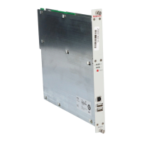
The RM2-DP12 and the PROFIBUS are connected via a 9-pin D-Sub plug
which, for security reasons, should be screwed to the RM2-DP12's D-Sub
socket. The X71 connection for the PROFIBUS is located on the front
panel.
The pin assignment corresponds to the PROFIBUS standard.
PROFIBUS-DP X71 connection
Pin Name Significance
1 - n.c.
2 - n.c.
3 B_LTG Receiving/sending data - P
4 RTS_SIG Repeater control signal
5 GND_ISO Data ground
6 P5V_ISO Supply voltage +
7 - n.c.
8 A_LTG Receiving/sending data - N
9 GND_ISO Repeater control signal
Fig.4 Pin assignment PROFIBUS-DP
At the PROFIBUS-DP X71 connection, up to 100 mA can be picked up
externally from P5VISO.
 Loading...
