M
1
M
1
M
1
M
1
F
4
12 131110987654312
21
24
43
1
u2
m2
b
a
s2
e0
N
L1
a1
f1
h1
current path
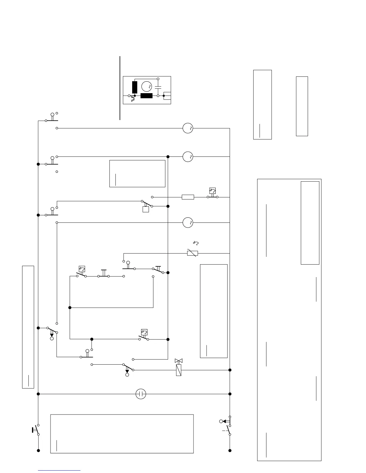
Symbol Key
current path
a1 ON/OFF SWITCH 2
e0 DOOR SWITCH 3
A2 ACTUATOR (Dispenser) 9
e6 FLOAT SWITCH 7
e5 FLOW SWITCH 11
f3 THERMOSTAT 135˚F 8
f1 WATER LEVEL SWITCH 5
f4 THERMOSTAT 149˚F 6
Symbol Key
HIGH TEMPERATURE b1
REGULAR TEMPERATURE none
RINSE & HOLD b3
f5 HIGH LIMIT 185˚F 11
current path
h1 ON/OFF LAMP 4
m1 TIMER MOTOR 12
m2 CIRCULATION MOTOR 13
m3 DRAIN MOTOR 10
r1 HEATING ELEMENT 11
s2 WATER SOLENOID 5
u– TIMER CONTACTS –
Selector Switch Contacts
L
permanent split
capacitor motor (m2)
N
u6
m1m3
b
a
u4
b
a
e5
24
1
185˚F
f5
r1
e6
2
1
u5
b
a
149˚F
f4
135˚F
f3
b1
1
2
b3
5
34
u3
b
a
PTC
A2
SHU 303X/313X
NOTE: Use timer to select wash
program and selector switch to
select water temperature.
To locate each part, match current
path from this table with current path
along bottom of circuit diagram above.
HINT: Float switch e6 switches from terminal 2 to 4 only if
dishwasher has overfilled or water has flooded the base.
HINT: Thermostats f3 & f4 with timer
contacts 3a & 5b (during heating/drying),
timer contact 4a (during rinsing), water level
switch f1 (after water has filled) and timer
contact 6a all advance timer motor m1.
HINT: Diagram
shows circuit at
“Regular
Temperature”
setting with
power off. Timer
contacts (u2-u6)
change position
(to “a” or “b”)
according to
timing chart
(Diagram) #64.
At “High
Temperature”
setting, contact
“b1” opens to
cut out
thermostat f3
allowing
thermostat f4 to
operate. At
“Rinse & Hold”
setting, contact
“b3” switches
from terminal 3
to 4, bypassing
thermostats f3 &
f4 and dispenser
actuator A2.
HINT: Flow
switch e5
switches
from
terminal 2
to 4 when
water is
circulating,
allowing
the heater
to work.
 Loading...