97
IX.
IX.
Wiring Diagrams/Tech Sheet
Wiring Diagrams/Tech Sheet
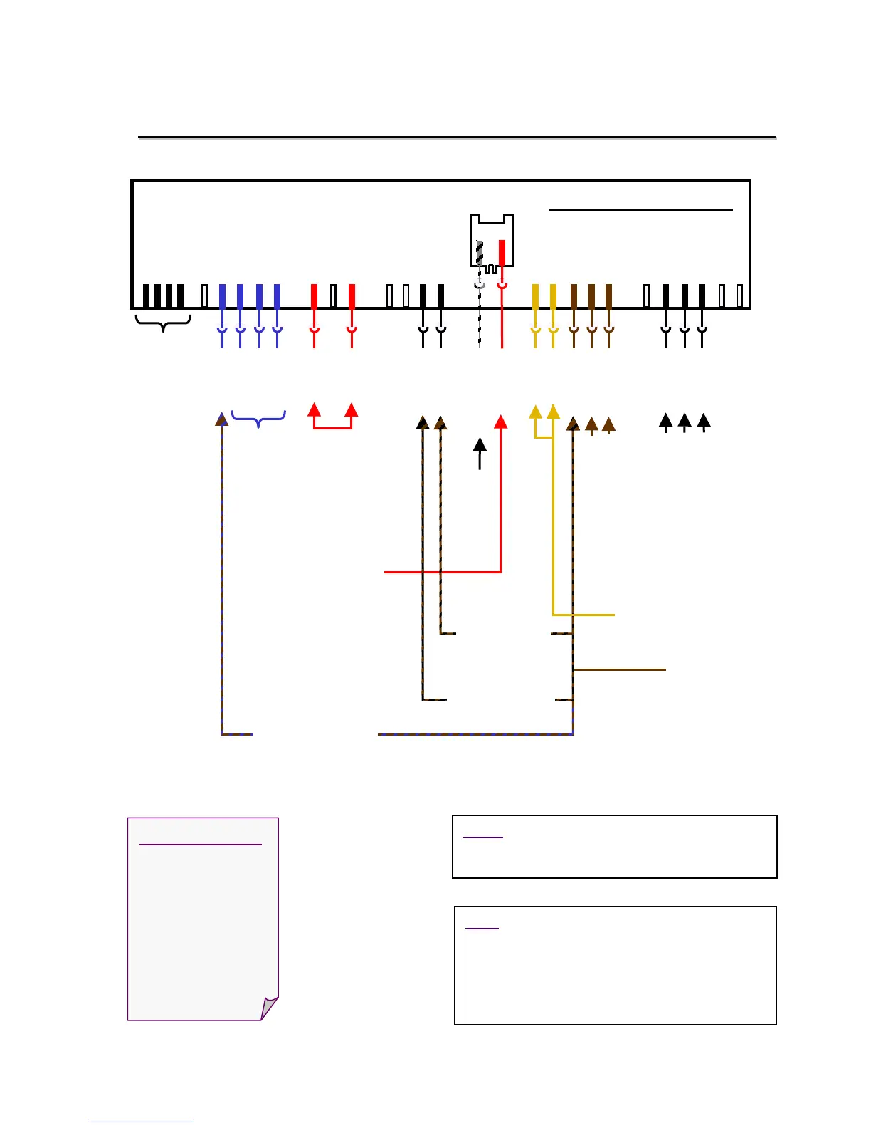
Measuring SHX33A/43E/46A/B, SHV46C Resistances @ Modules
Measuring SHX33A/43E/46A/B, SHV46C Resistances @ Modules
Control Module – I2
12345453452312
12
12
1
2
I2.
.5-
.4- .3-
.7-
.1-.2-
BU-I5-1
BU-I5-4
BU-I5-2
BU-I5-3
YE-e3
YE-e3
WH-I5-5
WH-I5-6
RD-I6-9
GYBK-a1-3
YE-A2
BN-e1-1
BN-e1-4
BN-I5-5
BN-I5-6
BN-a1-5
Measure
rinse-aid
sensor
(~ .4Ω)
Measure dispenser
actuator (~ 2150Ω)
To Aqua
Sensor
To hot line
To heater, Hi-Limit
& flow switch
To neutral
line
Resets control module
To water level switch
To water fill valve
To on/off switch
.6-
x2
Not used
on these
models
3
34
YE-A2
1
BN-I5-5
6
Measure NTC
(~ 55kΩ @ 72ºF)
Not used
Measure
drain motor
(~ 16.5Ω)
Measure
circulation
motor (~ 10Ω)
NOTE: This control module measures the NTC
differently – measuring voltage (NTC - neutral)
instead of current.
Wire color codes:
BK = Black
BN = Brown
BU = Blue
GY = Gray
RD = Red
WH = White
YE = Yellow
HINT: Water valve and drain motor can be
measured from front of dishwasher without
accessing control module wire harnesses.
Resistances are:
• Water valve ~ 1 k
• Drain motor ~ 16.5