31
Bosch Security Systems 09/07 BLCC500R FTR1.02
Copyright © 2007 E&OE
Test RF Device
MENU 3-3-2
Inputs > Global Input Options >
EOL Value
MENU 3-4-0
0 = No EOL
5
1 = 1K0 6 = 4K7 11 = 6K8 Alarm with 2K2 Tamper
2 = 1K5 7 = 5K6 12 = 10K Alarm with 10K Tamper
3 = 2K2 8 = 6K8 13 = 22K
4 = 2K7 9 = 8K1 14 = 3K3 with 6K8 Tamper
5 = 3K3 10 = 10K 15 = Split EOL (Parallel)
(3K3 = Primary 6K8 = Secondary)
Enter 0 - 15 Then Press [OK] To Program Globally The EOL Resistor For
All Zones. (*** System Wide Parameter ***)
Inputs > Global Input Options >
Keyswitch Options
MENU 3-4-1
0 = Latching - All On/Off 5 = Momentary All On/Off
0
1 = Latching - All On 6 = Momentary - All On
2 = Latching Part On/Off 7 = Momentary - Part
On/Off
3 = Latching - Part On 8 = Momentary - Part On
4 = Latching Off 9 = Momentary - Off
Enter 0 - 9 Then Press [OK] To Program How The Keyswitch Will
Operate. (*** System Wide Parameter ***)
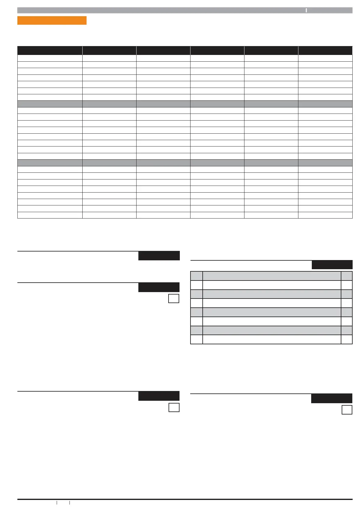
Table 19: Zone Defaults
Inputs > Global Input Options >
Input Options MENU 3-4-2
1 Tamper On Short N
2 Reserved N
3 Response Time 500ms N
4 Reserved N
5 Keyswitch Open / Close Report Y
6 Alarm On Tamper N
7 Reserved N
8 Reserved N
This location is a Bit option field. Press Keys [1] – [8] to turn ON and
OFF the required options. The option is selected or ON when the
coresponding zone indicator is on. Press [OK] To Save when finished.
(*** System Wide Parameter ***)
Inputs > PGM Input >
Input Type
MENU 3-5-0
0 = Disabled
0
1 = Latching - On/Off (RF Relay)
2 = Momentary - On/Off (RF Relay)
3 = Digiflex RF On/Off 6 = Ness Serial RF Receiver
4 = Bosch Serial RF Receiver 7 = Inovonics Serial Receiver
5 = Reserved 8 = Secure Wireless Receiver
Enter 0 - 7 + [OK] to select the interface method used for the given RF
receiver.