CC408 | Quick Reference Guide | 5. Wiring Diagrams EN | 22
Bosch Security Systems | 6/04 | 4998152468B
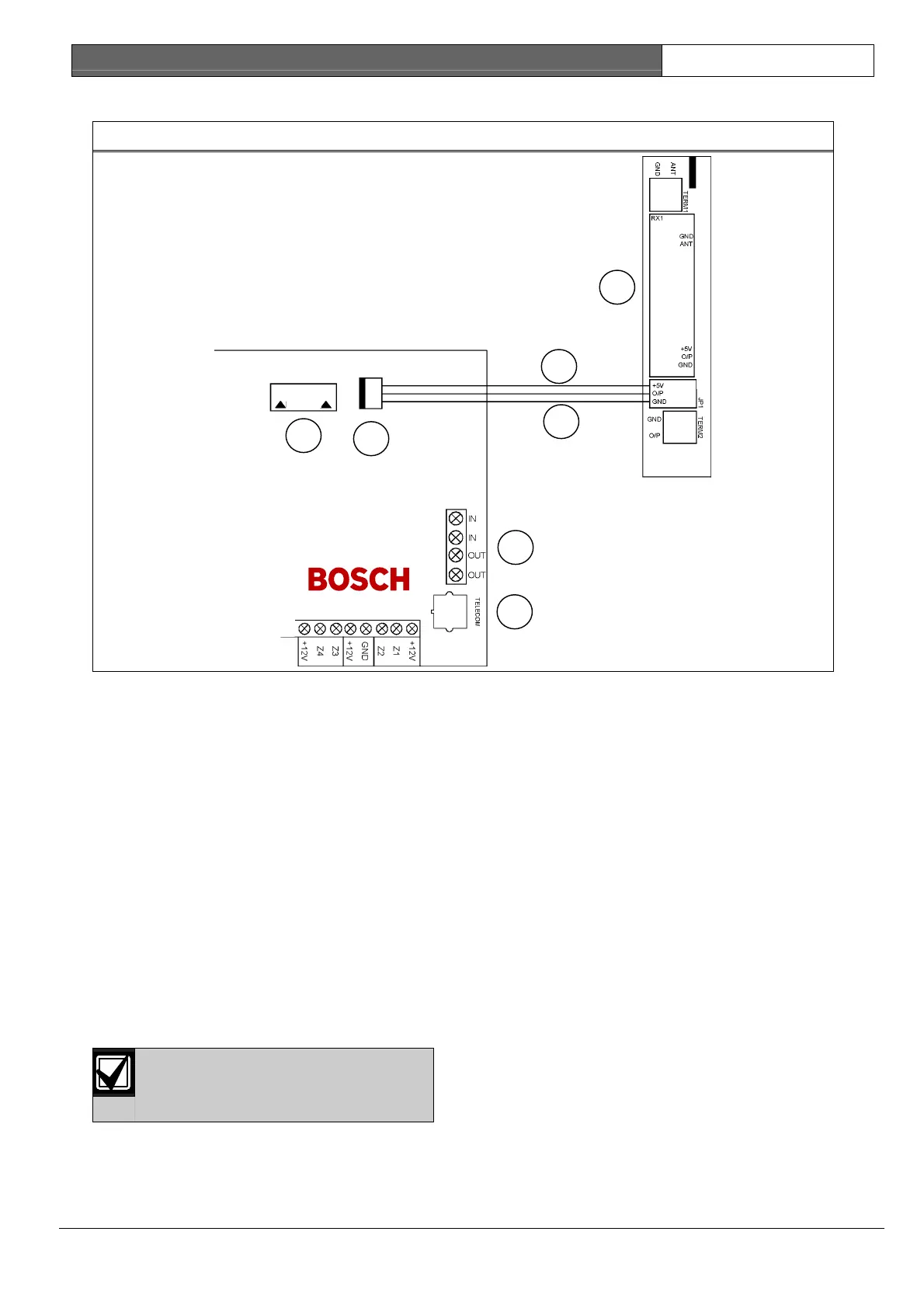
Figure 8: Solution Wireless On/Off Interface
1
2
3
4
5
6
7
1 – Phone amplifier or direct link cable
2 – Receiver interface connection
3 – Solution wireless on/off interface
4 – Red
5 – Black
6 – Termination for phone line
7 – Socket for telecom lead connection
5.1 Codepad Connections for
Partitioning
If the CP-5 Area Addressable (CP500A) codepad
is assigned to Area 1, DIP Switch 1 on the back of
the remote codepad must be in the ON position.
The following locations for Output 1 must be
programmed:
[LOCATION 368 = 6, 369 = 0]
If the CP-5 Area Addressable (CP500A) codepad
is assigned to Area 2, DIP Switch 2 on the back of
the remote codepad must be in the ON position.
The following locations for Output 1 must be
programmed:
[LOCATION 368 = 6, 369 = 1]
A master partitioned codepad requires
all DIP switches to be set to the ON
position.
The following DIP Switch settings and locations
must be programmed for the two CP-5 Area
Addressable (CP500A) codepads to function
correctly:
• AREA 1 CODEPAD – DIP Switch 1 on the
back of the remote codepad must be in the
ON position. The following location also must
be programmed:
[LOCATION 432, Option bit 2 must be
enabled]
• AREA 2 CODEPAD - (Output 1) – DIP
Switch 2 on the back of the remote codepad
must be in the ON position. The following
locations for Output 1 must be programmed:
[LOCATION 368 = 6, 369 = 1]