6 720 818 788 (2015/11)
6 | Instructions regarding the appliance
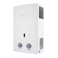
2.8 Appliance construction
Fig. 2
[1] Flue pipe connection
[2] Control device of the combustion gases
[3] Chimney
[4] Temperature limiter
[5] Combustion chamber
[6] Ignition probes
[7] Burner
[8] Ignition unit
[9] Gas flow regulator
[10] Temperature Sensor (for WD model only)
[11] Electro valve 1
[12] Outlet hot water
[13] Gas inlet
[14] Fixation point
[15] Ionization probe
[16] Water flow regulator
[17] Batteries case
[18] Bleeder screw (pressure relief)
[19] Cold water inlet
1
2
3
5
6
4
7
8
9
15
14
10
12
11
13
6720818788-07.1V
16
17
18
19
 Loading...
