13
Installation
Tronic – 6 720 884 457 (2018/02)
5.5 Electrical connections
All adjusting devices, verification and safety mechanisms were
submitted to a rigorous test in factory and are ready to work.
Before connecting to the power supply network,
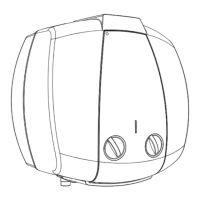
▶ Install a power supply cord in the water heater, with a min.
diameter of 1.5 mm2 (H05VV-F 5G 1.5 mm2). To do this,
the protective plate must be removed from the water
heater.
In the electrical installation, please install a disconnect switch
to separate all poles from the power supply network in
accordance with the national regulations.
Fig. 10 Removing the protective cover
If the pressure at the cold water inlet is
superior to that of 80% of the maximum
pressure of the appliance at, ie: 6,4 bar:
▶ Install a reducing valve (Fig. 8).
The safety valve will trigger every time the
water pressure in the appliance exceeds 6,4
bar. A facility for draining the expelled water
must be provided.
DANGER:
By electrical discharge!
▶ Before working on the electrical
components, firstly cut the power,
(fuse, circuit breaker or other).
CAUTION:
Electrical protection!
▶ The appliance should dispose of an
independent connection to the DB
board (electric board), protected by a
30 mA differential circuit breaker and
earthing.
The electrical connection must be realized in
accordance with the current country laws
regarding electrical installations.
 Loading...