10
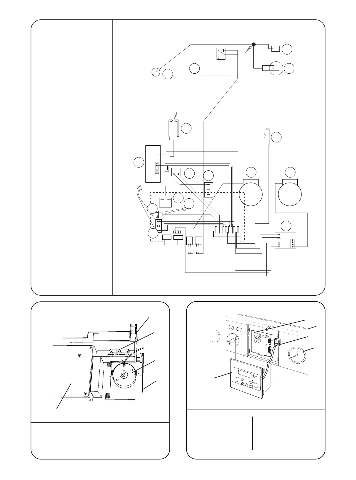
Fig 13 - Pictorial Wiring Diagram
13
14
15
16
12
1110
9
8
7
6
5
1
3
2
6 Grouped
Wires
to Top of
Boiler
From
Connection
ST12
Brown
Blue
To Flow Switch
2 Green
2 Pink
2 Orange
2 Red
6 Wires
from
Bottom
of
Boiler
2 Red
2 Orange
Green
Brown
Blue
Brown
Violet
Gr/Yellow
Blue
Brown
Black
Gray
White
Green/Yellow
Blue
Brown
White
Pink
Black
Black
White
Red
Blue
Brown
ST23
MAINS
IN
ST1
LINK
ST8
ST15
Yellow
Black
Black
Red
White
1. Spark Generator
2. 6 Way In-Line Connector
3. 2 Way In-Line Connector
4. Gas Valve
5. Flow Switch
6. DHW Sensor
7. Spark Electrode
8. Sense Electrode
9. System Pressure Switch
10. CH Pump
11. DHW Pump
12. Pump Relay PCB
13. CH Sensor
14. Fan
15. Overheat Cut-Off Thermostat
16. Air Pressure Switch
Fig 15 - Replacement Fuses
1
2
3
4
5
1. Control Panel Pivot 4. Facia Panel
Point 5. Control Board
2. Fuses-F1,F2 Assembly
3. Pressure Gauge
Fig 16 - Programmer Connection
6
5
4
3
1
2
1. Programmer
2. Programmer
Fixing Clip
3. Pressure
Gauge
4. Programmer
Connector
5. Facia
6. Control
Board
4
Grey
Yellow