12
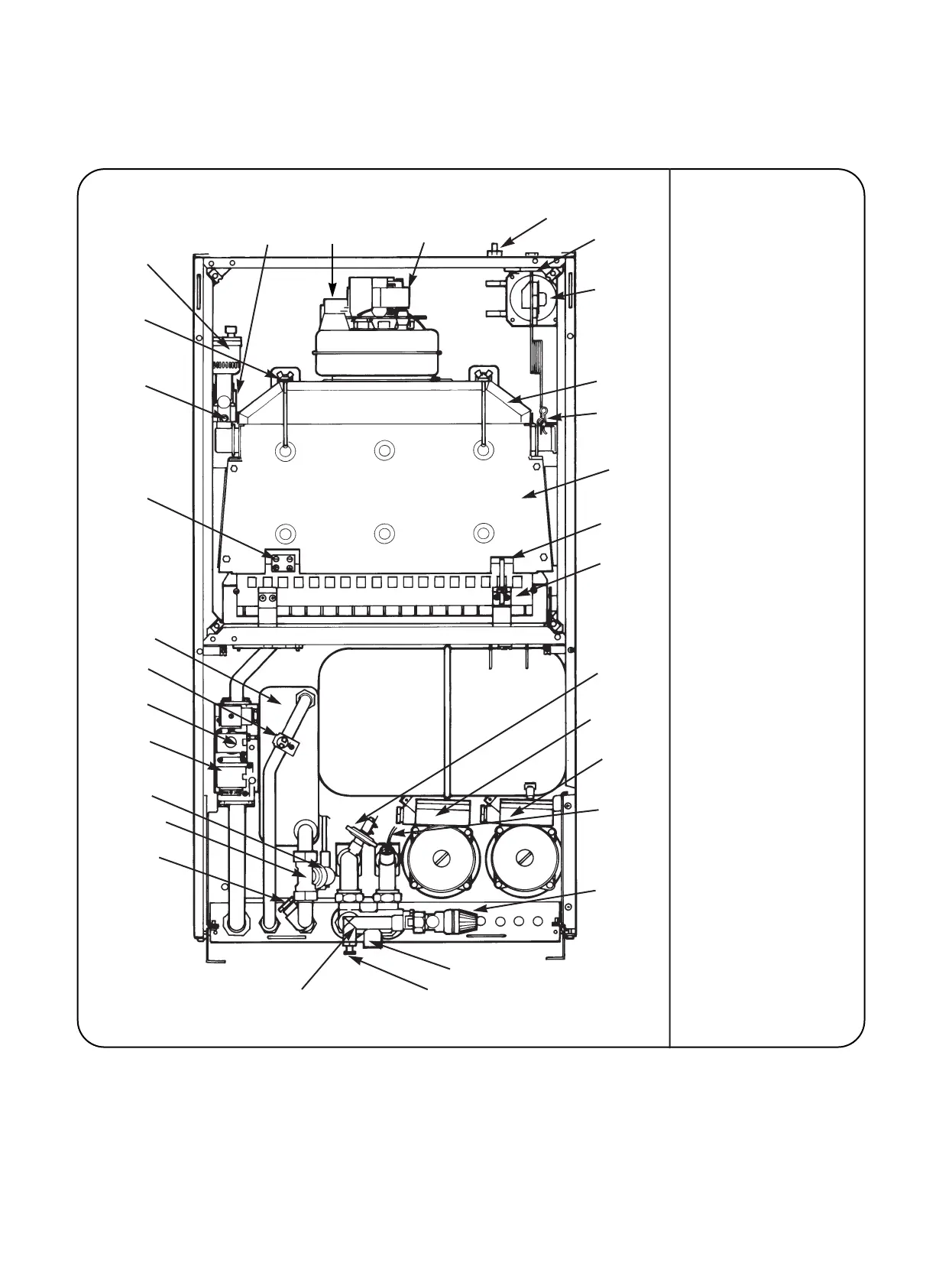
Fig 17- Front View of Appliance (control panel removed)
1-Fig 22
2-Fig 23
3
4-Fig 57
30-Fig 55
29-Fig 55
28-Fig 42
27-Fig 36
26-Fig 43
25-Fig 59
24-Fig 56
23-Fig 46
22-Fig 40
21-Fig 50
20-Fig 49
19-Fig 49
17-Fig 41,27
16-Fig 41
15-Fig 27
14-Fig 27
13-Fig 38
12-Fig 38
11-Fig 51
10-Fig 45
9-Fig 44
8
7-Fig 57
6-Fig 42
5-Fig 61
1. Fan & Flow Sensor
2. Fan Connections
3. Combustion Products
Test Point
4. Overheat Thermostat
5. Air Pressure Switch
6. Flue Hood
7. Overheat Thermostat Phial
8. Combustion Chamber Cover
9. Flame Sense Electrode
10. Burner
11. System Pressure Switch
12. Central Heating Pump
13. Domestic Hot Water Pump
14. Pressure Gauge Connection
15. Relief Valve
16. Bypass Adjuster
17. Drain Point
18. Flow/Return Manifold
19. Domestic Hot Water
Expansion Vessel
Connection (optional)
20. Domestic Hot water
Control Assembly
21. Domestic Hot Water Flow
Switch
22. Gas Valve
23. Modureg Pressure Adjuster
24. Domestic Hot Water Sensor
25. Domestic Hot Water Heat
Exchanger
26. Spark Electrode
27. Primary Flow Manifold
28. Flue Hood Fixing
29. Auto Air Vent
30. Primary (CH) Sensor)
18-Fig 27