EasyManua.ls Logo

Bosch WTD 12-3 AME 31 User Manual

Bosch WTD 12-3 AME 31
45 pages
To Next Page IconTo Next Page
Page #1 background imageLoading...
Page #1 background image
Page 1 from 45 6 720 887 546 “SM FP_ErP LPP/MPP Europe 2018/05 en”
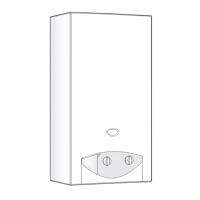
LOW NOX INSTANTANEOUS
GAS WATER HEATER
ROOM SEALED FAN ASSISTED / PRESSURIZED
GAS WATER HEATER
FOR INDOOR INSTALLATION
TRAINING AND SERVICE INFORMATION FOR AFTER SALES
This document is restricted to exclusive use by the official service partners. Each
country should adapt the manual and its contents to the available range.

Other manuals for Bosch WTD 12-3 AME 31

Questions and Answers:

Bosch WTD 12-3 AME 31 Specifications

General IconGeneral
Gas TypeNatural gas
Ignition TypeElectronic ignition
Frequency50 Hz
TypeFlow-through water heater
Mounting TypeWall mounted
ThermostatYes
Safety FeaturesFlame failure device, overheating protection

Summary

Installation

Components Overview

Control panel

Explains the function of the control panel for user, installer, and technician operations.

Heat Cell and Burner Components

Heat cell with burner pipes

Describes the heat cell, including heat exchanger, burner, and electrodes.

Gas Manifold

Fan and Gas Valve Components

Heat Exchanger Component

Temperature Sensors

Water Flow Measurement

Water Flow Sensor

Details the turbine flow sensor, its operation, and characteristic curve.

Ignition and Ionization System

Ignition electrode

Explains the ignition electrode's function in spark generation and safety timing.

Ionization electrode

Describes the ionization electrode's role in sensing flame presence.

Working Principle

Operational Modes and Safety

Power reduction in case of high temperature risk

Details strategies for reducing power to prevent overheating and scalding.

Electronic Control Unit (ECU) - MPP

Overview of ECU (electronic control unit) MPP

Presents the electrical diagram and components of the MPP electronic control unit.

Electronic Control Unit (ECU) - LPP

Overview of ECU (electronic control unit) LPP

Presents the electrical diagram and components of the LPP electronic control unit.

Sensor Resistance Values

Service and Configuration

Service

Outlines procedures for entering service mode and performing configurations.

Gas Power Adjustment

Gas Power Adjustment Parameters

Details adjustments for minimum/maximum power operation.

Combustion Power Adjustments

Access to combustion adjustments

Guides on accessing combustion adjustment parameters.

P1 Maximum power burner adjustment

Adjusts maximum burner power after component replacement or conversion.

P2 Minimum power burner adjustment

Adjusts minimum burner power after repairs or conversion.

Settings and Diagnostic Modes

Diagnostic mode and visualization mode

Accesses diagnostic and visualization data for troubleshooting.

Data Visualization Modes

Last 10 Failures for diagnostic purposes

Lists the last 10 recorded failures for diagnostic purposes.

Maintenance

Maintenance

Provides recommendations for appliance checks and servicing.

Maintenance Procedures

Troubleshooting - Error Codes (Part 1)

Error code definition

Lists error codes and their definitions for troubleshooting.

Error code type

Categorizes error codes as self-resolving or requiring action.

Water temperature sensors defective

Describes troubleshooting for defective water temperature sensors.

Box temperature protection

Explains actions taken for box over-temperature protection.

Air temperature sensor opened circuit

Details issues with open circuit air temperature sensors.

Outlet water temperature sensor defective

Describes troubleshooting for defective outlet water temperature sensors.

Signal from fan not received

Explains troubleshooting when no fan signal is received.

Water flow signal over specified maximum value

Addresses issues with water flow signals exceeding specified maximum values.

Exhaust blockage

Explains troubleshooting for exhaust blockage detection.

Over-temperature detected

Details actions for detected over-temperature conditions.

Inlet water temperature sensor defective

Describes troubleshooting for defective inlet water temperature sensors.

Troubleshooting - Error Codes (Part 2)

Temperature limiter or thermal fuse opened circuit

Troubleshoots open circuits in temperature limiters or thermal fuses.

No ionization during safety time (safety timeout)

Addresses the error when no ionization signal is detected during safety time.

Gas valve wrong connection

Explains errors related to incorrect gas valve connections.

Wrong gas type

Details issues arising from an incorrect gas type setting.

Ionization error

Describes troubleshooting for ionization errors.

Leakage on gas valve

Explains how to detect and resolve gas valve leakage.

Ionization loss

Addresses issues related to ionization signal loss.

Troubleshooting - Error Codes (Part 3)

Solenoid valve drive circuit

Troubleshoots errors in the solenoid valve drive circuit.

MCU PC (micro controller) instruction error

Addresses errors in the micro controller's instruction processing.

Instructions compile and execution error

Troubleshoots errors in instruction compilation and execution.

MCU RAM DC (micro controller) internal error

Addresses internal errors in the micro controller's RAM.

APS I/O short circuit error

Troubleshoots short circuit errors in APS I/O.

MCU ROM (micro controller) error

Addresses errors in the micro controller's ROM.

MCU registration DC (micro controller) error

Troubleshoots registration errors in the micro controller.

Remote controller error

Addresses errors related to the remote controller function.

Lock function self-check error (PCB internal error)

Troubleshoots self-check errors within the PCB.

Related product manuals