1.0 Specifications
• Input Power: 9 to 15 VDC, 6 mA nominal (35 mA with LED on).
• Standby Power: There is no internal standby battery. Connect to standby power as a backup in the event primary power
fails. Six mA-H required for each hour of standby time needed. Four hours minimum is required for UL Listed Requirements.
• Temperature: The operating temperature range is -20° to +120°F (-29° to +49°C). For UL Listed Requirements, the
temperature range is +32° to +120°F (0° to +49°C).
• Microwave Frequency: 10.525 Ghz, ±25.000 Mhz.
• Coverage: 35 ft. by 35 ft. (10.7 m by 10.7 m)
• Internal Pointability: +2° to –10° Vertical, ±10° Horizontal.
• Tamper: Tamper condition transmitted through the Zonex bus when the cover is removed.
• Requirements: Requires a compatible control panel with a POPEX module installed.
• Options: B328 Gimbal Mount Bracket, B335 Low Profile Swivel Mount Bracket (use of a bracket may reduce range and
dead zone areas).
• U. S. Patent Numbers: #4,660,024; #4,764,755; #5,077,548; #5,208,567; #5,262,783; #5,450,062. Other patents pending.
2.0 Installation Considerations
• Never install the detector in an environment that causes an alarm condition in one technology. Good installations start with
the LED OFF when there is no target motion. It should never be left to operate with the tri-color LED in a constant or
intermittent green, yellow, or red condition.
• Point the unit away from outside traffic (roads/alleys). Remember: Microwave energy will pass through glass and most
common non-metallic construction walls. Avoid installations where rotating machines (e.g., ceiling fans) are normally in
operation within the coverage pattern.
• Point the unit away from glass exposed to the outdoors and objects that may change temperature rapidly. Remember: The PIR
detector will react to objects rapidly changing temperature within its field-of-view.
• Eliminate interference from nearby outside sources.
3.0 Mounting
1. Select a location likely to intercept an intruder moving across the
coverage pattern. The surface should be solid and vibration free.
Mounting height range is 6 to 8 ft. (1.8 to 2.4 m). Recommended
mounting height is 6.5 ft. (2 m).
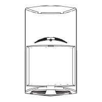
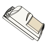
2. Remove the cover. Insert a flathead screwdriver into the locking tab
hole at the bottom front of the detector. Pull the cover up and forward.
3. Mount the unit with the terminal block up.
4. Remove the circuit board from the base. Loosen the Vertical Adjust
Screw and slide the circuit board down then out.
5. Break away the appropriate thin-wall wire entrance and mounting
hole coverings in the base.
6. Using the base as a template, mark the location of the holes on the
mounting surface.
7. Route wiring (unpowered) as necessary. Route to the rear of the base and through the wire entrance.
8. Firmly mount the base to the mounting surface. Return the circuit board to the base and tighten the Vertical Adjust Screw.
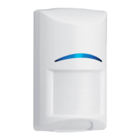
Microwave PIR Detector with POPIT Interface ZX835
Installation Instructions