15
802C DISASSEMBLY PROCEDURE
COVER AND TOP PCB REMOVAL:
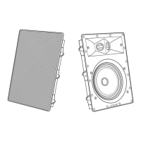
NOTE: The 802C
contains
two
(2)
printed
cir-
cuit
boards, one
mounted
on top
of
the
oth-
er.
The
tOt
board
is
for
the
302
Output
(Pas-
sive
Mode.
This board may be removed for
troubleshooting
the
lower PCB. With
the
top PCB removed,
the
802C will function
in
the
802
Full-Range
Mode.
If
removal
of
the
top PCB
is
necessary,
follow
the
steps
below.
I. Using a Phillips-head
screwdriver,
locate
and
remove
the
four (4)
screws
holding
the
cover
in
place,
and
remove
the
cover.
2.
Locate
the
four (4)
plastic
stand-offs.
(Three
are
located
in
a
corner
of
the
PCB and
the
fourth
is
located
between
C
125
& C225).
3. With small needle-nose pliers,
squeeze
the
retaining
tab
of
each
CORNER-MOUNTED
stand-off
and
lift
the
PCB
up
slightly from
the
stand-off
to
release
the
lock. .
4. Grasp
the
PCB
at
the
midpoint
of
each
side, and with needle-nose pliers on
the
fourth
stand-off,
gently
rock
the
board up-
ward
off
the
connecting
pins and
out.
NOTE:
DO
NOT
angle
the
PCB sharply; pos-
sible
damage
could
occur
to
connecting
pins.
LOWER PCB REMOVAL:
NOTE: It
is
not
necessary
to
remove
top
PCB
for
lower PCB removal.
I.
Locate
and
remove
the
five (5)
screws
holding
the
PCB
in
place.
2.
Remove
the
six (6) knurled nuts holding
the
phone
jacks.
3.
Looking
at
the
front
of
each
XLR con-
nector,
there
is
a small hole
that
is
not for
signal purposes. It
is
located
under
the
re-
lease
tab
of
the
connector.
Insert a small
flat-blade
screwdriver
(possibly a
jeweler's
screwdriver),
into
the
small hole, and
rotate
the
screw
1/8
turn
counterclockwise.
This
will
release
the
lock.
4.
Angle
the
PCB
out
of
the
XLR
connector
mount,
and
lift
the
PCB
out
of
the
chassis.
REASSEMBLY PROCEDURE
LOWER PCB
INST
ALLATION:
I. Align
the
lower PCB up with
the
XLR
connectors
and
the
screw
mounting posts.
2.
Refasten
the
lower PCB
to
the
chassis
with five
(5)
screws.
3.
Looking
at
the
front
of
each
XLR
con-
nector,
there
is
a small hole
that
is
not for
signal purposes. It
is
located
under
the
re-
lease
tab
of
the
connector.
Insert a small
flat-blade
screwdriver
(possibly a
jeweler's
screwdriver), into
the
small hole, and
rotate
the
screw
1/8
turn
clockwise. This will lock
the
connectors
in
place.
4.
Install
the
six
(6)
knurled nuts back on
the
phone jacks.
TOP PCB
INST
ALLATION AND COVER:
NOTE:
DO
NOT
angle
the
PCB sharply; pos-
sible
damage
could
occur
to
connecting
pins.
I. Grasp
the
top board
at
the
midpoint
of
each
side, and align
the
board
to
the
four
(4)
stand-offs
and
connecting
pins.
2.
Gently
lower
the
PCB down
on
the
con-
necting
pins and
stand-offs
until
the
stand-
offs
are
locked
in
place.
3. Position
cover
into place and
secure
with
the
four (4)
screws.
220- To IIO-VOLT CONVERSION
NOTE: Conversions must be
performed
with
the
line cord disconnected from any power
source.
I. Follow
the
steps
in
the
Disassembly
Pro-
cedure
to
remove
bottom
PCB.
2.
Locate
jumper LK-31
in
front
of
the
po-
wer
transformer
(near
the
line cord), and
re-
move. (See Fig. 20.)
3.
Add jumpers LK-32 and LK-33.
4.
Remove
220-volt line cord (if supplied)
and
replace
with 1I0-volt line cord. Make
certain
the
line cord
is
properly installed
in
 Loading...