10
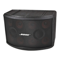
302 SIGNAL TEST PROCEDURE:
Connect
a sine wave
oscillator
to
a
power
amplifier.
Adjust
the
frequency
of
the
oscil-
lator
to
15Hz.
Adjust
the
amplifier
output
to
10 volts rms and
connect
to
the
input
jack.
No
extraneous
noises such
as
rubbing,
scrap-
ing, or
ticking
should
be
heard,
other
than
normal suspension sounds. Sweep
the
oscil-
lator
from 15Hz
to
250Hz, assuring
that
no
extraneous
noises
are
present.
302 CROSSOVER TEST PROCEDURE:
Set
oscillator
to
200Hz and
reduce
the
amp-
lifier
output
to
2 volts rms.
Place
a phone
jock
with
an 8-ohm RESISTIVE load
into
one
of
the
output
jacks, and
measure
the
output
voltage
across
the
resistor:
.'3
to
.5
volts.
Set
oscillator
frequency
to
IkHz, and
mea-
sure
the
output
voltage
across
the
8-ohm
re-
sistor:
1.6
to
2.1
volts.
Repeat
the
same
steps
for
the
second
output
jack
to
assure
BOTH
crossover
networks
are
functioning
correctly.
302 PHASING CHECK:
Usi ng a
6-
to
12
-vo
It dc power suppIy,
check
that
both
speakers
are
in
phase
by
placing
the
positive
portion
of
the
supply
to
the
tip
terminal
of
a phone
jack
and
the
negative
portion
to
the
sleeve.
Apply
to
the
input
jack
of
the
302. Both woofers should move
outward.
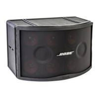
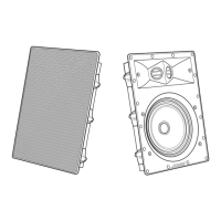
302 DRIVER REPLACEMENT PROCEDURE
I.
Remove
the
fourteen
(14)
screws
of
the
back-access
compartment.
NOTE: The
screw
heeds
are
Pozidriv
and
NOT Phillips. Using a Phillips
bit
could
dam-
age
the
screw
heads. Make
certain
you use
a
112
Pozidriv
bit.
screws.
6.
Connect
the
red/black
harness to
the
speaker
terminals.
(Red
is
positive;
black
is
negative.)
7.
Perform
test
procedure
to
assure
the
repair
is
completed.
8.
Secure
the
access
compartment
with
the
fourteen
(
14)
screws.
302 CROSSOVER COMPONENT
REPLACEMENT
NOTE: Both
of
the
302
crossover
networks
supply
energy
to
the
802
speakers.
If
a 30?
is
brought
in for ANY
complaint,
each
cross-
over
newtork MUST
be
tested
to
assure
prop-
er
operation
of
the
system.
(See Trouble-
shooting
Guide.)
I.
Remove
the
fourteen
(14)
screws
of
the
back-access
compartment.
NOTE: The
screw
heads
are
Pozidriv
and
NOT Phillips. Using a Phillips
bit
could
dam-
age
the
screw
heads.
Make
certain
you use
a
112
Pozidriv
bit.
2.
Remove
the
access
compartment
panel,
and
untwist
the
service
loop
of
both
pairs
of
red/black
harness wires.
3.
Replace
the
defective
component.
4.
Perform
test
procedure
to assure
the
re-
pair
is
completed.
5.
Secure
the
access
compartment
with
the
fourteen
(14)
screws.
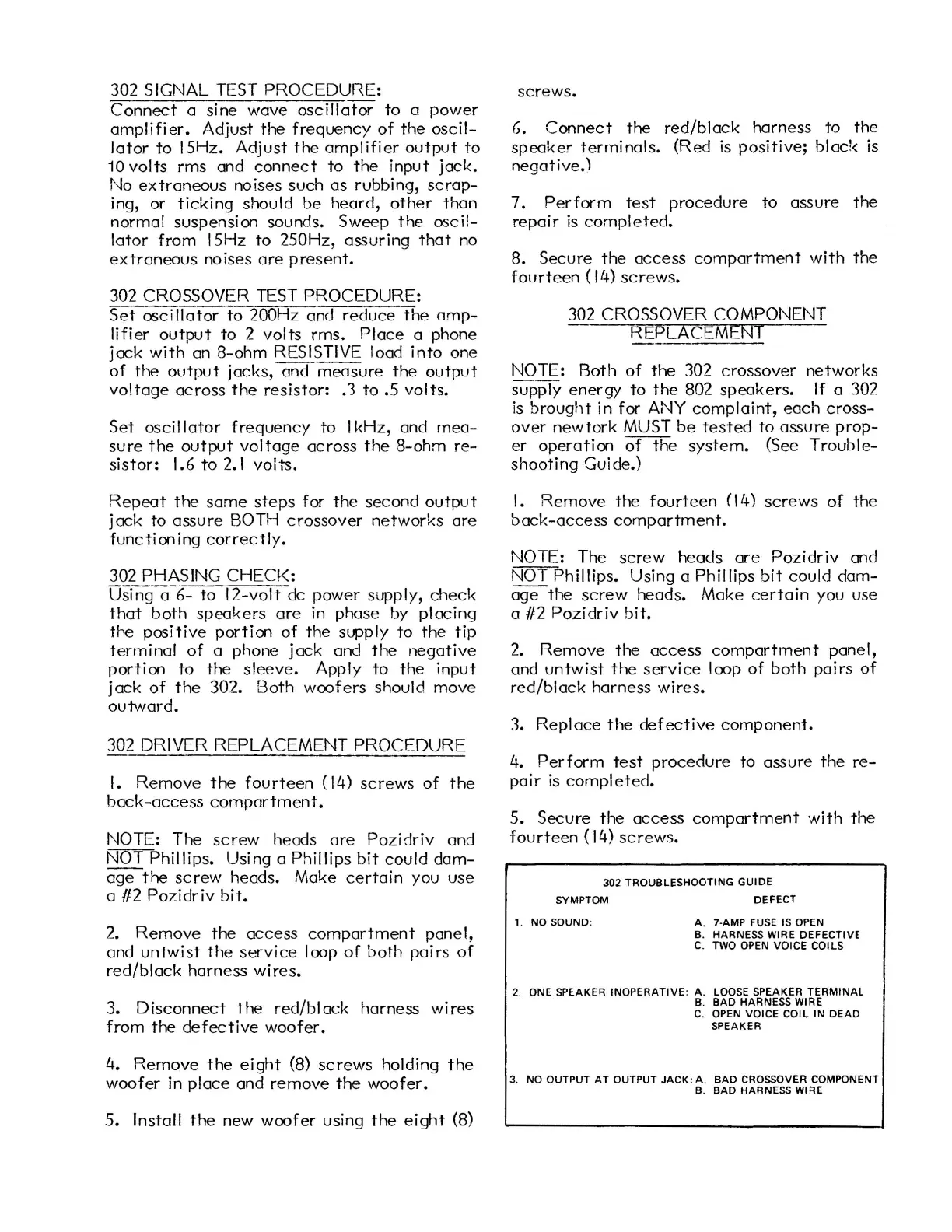
302 TROUBLESHOOTING
GUIDE
SYMPTOM DEFECT
2.
Remove
the
occess
compartment
panel,
and
untwist
the
service
loop
of
both
pairs
of
red/black
harness
wires.
1.
NO SOUND:
A.
7-AMP FUSE IS OPEN
B. HARNESS WIRE DEFECTIVE
C.
TWO OPEN VOICE COILS
3.
Disconnect
the
red/block
harness
wires
from
the
defective
woofer.
4.
Remove
the
eight
(8)
screws
holding
the
woofer in
place
and
remove
the
woofer.
5. Install
the
new woofer using
the
eight
(8)
2.
ONE SPEAKER
INOPERATIVE:
A. LOOSE SPEAKER
TERMINAL
B.
BAD
HARNESS WIRE
C.
OPEN VOICE COIL
IN
DEAD
SPEAKER
3. NO OUTPUT
AT
OUTPUT
JACK:
A.
BAD
CROSSOVER COMPONENT
B.
BAD
HARNESS WIRE
 Loading...