9
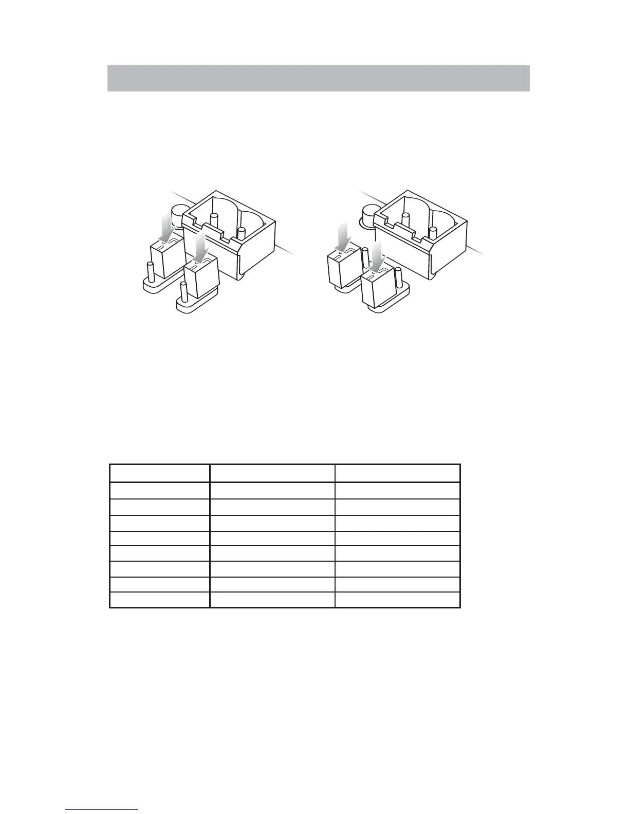
Power from power
connector setting
(Default)
Power from Ethernet
connector setting
Changing the power input jumpers
Power can be supplied directly to the 2-terminal Phoenix connector or over
the Ethernet cable. By default, the CC-64 is configured for power from the
power connector. If you choose power over the Ethernet cable, remove the
four screws on the rear cover and move the two jumpers as shown below.
Power over ethernet wiring
The following table lists the pin-outs for the RJ45 plug (on the cable) that is to
be used with the CC-64.
RJ45 Plug Wiring
RJ45 Plug Color Function
1 WHITE/orange Transmit Data+
2 ORANGE/white Transmit Data-
3 WHITE/green Receive Data+
4 BLUE/white Power (optional)
5 WHITE/blue Power (optional)
6 GREEN/white Receive Data-
7 WHITE/brown Ground (optional)
8 BROWN/white Ground (optional)
Connections