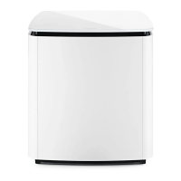
Do you have a question about the Bose Sub2 and is the answer not in the manual?
Steps for connecting the Sub2 to a standard power outlet.
Guide to connecting the Sub2 to an L1 Pro32 system.
Explanation of the auto-standby feature and its management.
Detailed description of the Sub2's ports and controls.
List of resistors for the MAIN-I/O PCB.
List of capacitors for the MAIN-I/O PCB.
List of diodes for the MAIN-I/O PCB.
List of inductors for the MAIN-I/O PCB.
List of transistors for the MAIN-I/O PCB.
List of integrated circuits for the MAIN-I/O PCB.
List of miscellaneous components for the MAIN-I/O PCB.
List of resistors for the POWER-AMP PCB.
List of capacitors for the POWER-AMP PCB.
List of diodes for the POWER-AMP PCB.
List of transistors for the POWER-AMP PCB.
List of integrated circuits for the POWER-AMP PCB.
List of miscellaneous components for the POWER-AMP PCB.
Procedures for disassembling the Sub2 Power Stand.
Steps for removing the I/O Panel Assembly from the unit.
Steps for removing the Power-Amp board from the unit.
Steps for removing the Main-I/O board from the unit.
Steps for removing the woofer assembly from the unit.
List of necessary tools and cables for testing.
Instructions for connecting the system for testing.
Verifying the operation of buttons and controls.
Tests for input and output signal verification.
Procedures for testing line output levels.
Verifying polarity and cardioid mode functionality.
Detailed testing of extended button and control functions.
Further testing of extended button and control functions.
Steps for performing the mandatory Hi-Pot electrical safety test.
Guide to updating the firmware of Bose products.
| Material | EVA (Ethylene Vinyl Acetate) |
|---|---|
| Case type | Trolley case |
| Closure type | Zipper |
| Suitable for | Subwoofer |
| Product color | Black |
| Carrying handle(s) | Yes |
| Surface coloration | Monochromatic |
| Brand compatibility | Bose |
| Number of records (max) | - |
| Width | - mm |
|---|


