29
DISASSEMBLY PROCEDURE
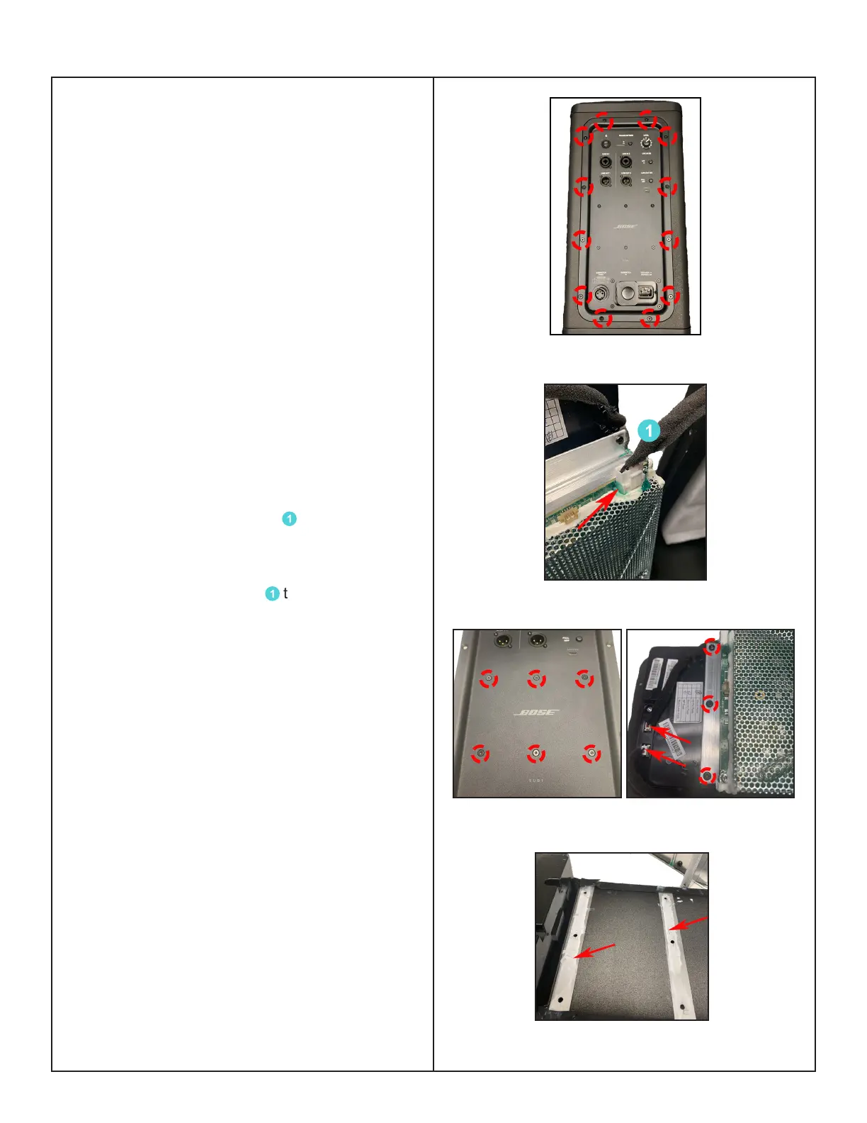
Figure 4. I/O Panel Screws Removal
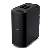
Sub2 Power Stand Procedures
CAUTION: The SMD integrated circuits used
on the Main-I/O Board are extremely sensitive
to ESD damage. Be sure to use an approved
and tested ESD strap that is properly grounded
to your work bench before attempting disas-
sembly or repair of the Sub2 Powered Bass
Module.
1. I/O Panel Assy Removal
1.1 Remove the 14 screws securing the
I/O Panel Assy as indicated in Figure 4.
Note: Be careful to not cause cosmetic
damage to the unit.
1.2 Incline the Power stand to let the I/O
panel assy go downwards.
1.3 Remove the green adhesive with IPA
(Isopropyl alcohol) from the
1
cable's
connections as red arrow indicated in Figure
5.
1.4 Disconnect the cable
1
that are attaching
the Woofer. Figure 5.
2. Power-Amp Board Removal
2.1 Perform procedure 1.
2.2 On the front of the I/O panel assy, remove
the 6 screws as indicated in Figure 6 (left) and
turn it over to remove the 3 screws securing
the Power-Amp board. Figure 6 (right).
2.3 Detach 2 cables' connections as red arrow
indicated in Figure 6 (right).
Re-assembly Note: The old Heat Sink ther-
mal grease must be removed with isopropyl
alcohol and the new thermal grease, GAP
FILLER, THERMAL, part number 749859-
0020 MUST be used during board replace-
ment. Failure to use the correct thermal
grease WILL cause thermal failures. Figure 7.
Figure 5. Green Adhesive & Cable Removal
Figure 6. Power-Amp Board Screws Removal
Figure 7. Heat Sink Thermal Grease