31
DISASSEMBLY PROCEDURE
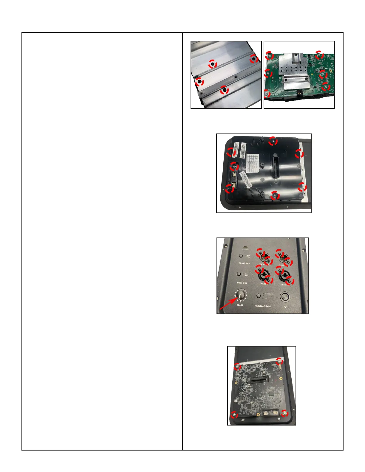
Figure 13. Fire Box Screws Removal
Figure 14. 4 Jacks Screws & Level Knob
Removal
2.7 Remove the 10 screws that secure the
Power-Amp board as indicated in Figure 12.
2.8 Remove the Heatsink from the PCBA.
Re-assembly Note:
The old power amp IC thermal grease must be
removed with isopropyl alcohol and the new
thermal grease, GAP FILLER, THERMAL, part
number 749859-0020 MUST be used during
board replacement.
The old Heatsink must be reused with the new
PCBA.
3. Main-I/O Board Removal
3.1 Perform step 2.
3.2 On the Fire box, remove the 7 screws
that secure the Main-I/O board as indicated in
Figure 13.
3.3 On the front of I/O panel assy, remove the
8 screws securing the 4 Jacks and Level Knob
as red arrow indicated in Figure 14.
3.4 Lift the Fire box up and remove the 4
screws securing the Main-I/O board. Figure15.
Re-assembly Note:
There are no Device ID concerns when re-
placing the main board. The Device ID is
assigned at the factory. Service replacement
Main-I/O PCBA’s use the PCBA serial num-
ber instead of the system serial number. As a
result, the system serial number will not show
up in the L1 Mix app.
Figure 15. Main-I/O Board Screws Removal
Figure 12. Power-Amp Board Screws Removal