AM262842_00_V.pdf December 20, 2001 7
Which Lifestyle
®
system do you own?
If you will be connecting your Lifestyle
®
powered speaker system to a Lifestyle
®
system, you
need to determine which system you own before attempting to connect the speakers.
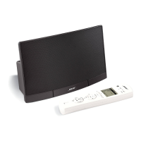
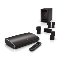
Identifying multi-room interface systems
Figure 5
Front and rear of the multi-room
interface, and Personal
®
music center
The multi-room interface allows you to connect up to four rooms or listening areas with
additional speakers. These systems are operated using a Personal music center. To connect
additional speakers to a multi-room interface, see “Connecting the speakers to multi-
room interface systems” on page 8.
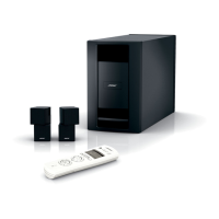
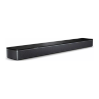
Identifying systems with the Lifestyle
®
media center
Figure 6
Front and rear of the Lifestyle
®
media center
The Lifestyle
®
media center includes a single-disc DVD/CD player and two mini-DIN speaker
output jacks on the rear panel. To connect additional speakers to the Lifestyle
®
media
center, see “Connecting the speakers to the Lifestyle
®
media center” on page 10.
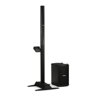
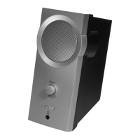
Identifying systems with the Model 20
music center
Figure 7
Front and rear of the Model 20
music center
The Model 20 music center includes a six-disc CD player and two mini-DIN speaker output
jacks, labeled ZONE 1 and ZONE 2, on the rear panel. To connect additional speakers to a
Model 20 music center, see “Connecting the speakers to the Model 20 music center”
on page 12.
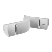
Identifying systems with the Model
5 music center
Figure 8
Front and rear of the Model 5
music center
The Model 5 music center includes a single-disc CD player and three pairs of RCA speaker
output jacks, labeled A, B, and FIXED, on the rear panel. To connect additional speakers to
a Model 5 music center, see “Connecting the speakers to the Model 5 music center” on
page 13.
Connecting the speakers
L
R
A
B
SPEAKERS
OUTPUT
TAPE
REC
PLAY
FIXED
INPUT
L
R
AUX
VIDEO
SOUND
ANTENNA
1
2
SYSTEM
CONTROL
SEE INSTRUCTION MANUAL
POWER
12VAC IN
1.0A
A
M
L
O
O
P
FM
75
Ω
L
IF
E
S
T
Y
L
E
®
M
O
D
E
L
5
M
U
S
IC
C
E
N
T
E
R
B
O
S
E
C
O
R
P
O
R
A
T
I
O
N
,
F
R
A
M
I
N
G
H
A
M
,
M
A
0
1
7
0
1
-
9
1
6
8
M
A
D
E
I
N
U
.
S
.
A
C
O
V
E
R
E
D
B
Y
U
.S
. P
A
T
E
N
T
D
3
3
9
,6
0
6
M
A
N
U
F
A
C
T
U
R
E
D
:
®
ANTENNA
FM AM
LOCATE
MUSIC
CENTER
BOSE CD
AUX VIDEO 1 VIDEO 2 TAPE IN OUT
LLLLL
RRRRR
RECORD
ROOM A
(PRIMARY)
ROOM B
ROOM DROOM C
POWER
SERIAL
DATA
!
SEE USER’S
GUIDE
12V AC
1.6A
AUDIO INPUT AUDIO OUTPUT
®
LR
TAPE IN
LR
TAPE OUT
OPTICALOPTICAL
DIGITAL
R
LLLLL
RRRR
DIGITAL DIGITAL DIGITAL DIGITAL
INPUT OUTPUT
AUDIO OUTPUTS
AUDIO INPUTS
ANTENNA
SPEAKER
ZONES
2
1
VIDEO INPUTS
POWER
TV
SENSOR
IR
EMITTER
SERIAL
DATA
FM
AM
RECORD TAPE AUX VCR TV
COMPOSITE S-VIDEO
VIDEO OUTPUTS
COMPOSITE S-VIDEO
75
Ω
33V
DC
1.1A
 Loading...