Page 14 Installation and Operating Guide English
Installation and Operating Guide pro.Bose.com
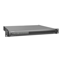
Controls, Display, and Connectors
Figures 1 and 2 detail the various elements found on the front and rear panels of PowerMatch
®
amplifiers.
Figure 1. Front Panel View
1
32
456
7 8
8
1
LED Indicators
5
Menu Soft Keys (1-5)
2
LCD Screen
6
USB connector
3
Navigation Soft Key
7
Front airflow intake vents
4
Rotary Encoder
8
Front rack-mount ears
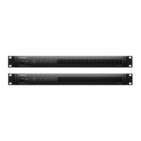
Figure 2. 4-channel and 8-channel Rear Panel Views
18 12 13
9
10 11 14 15 16 17 18
9
Analog Input connectors
14
Loudspeaker output connectors
10
Fault Notification Output
15
AC Mains receptacle
11
Ethernet RJ-45 network connector
(Network versions only)
16
AC Mains retention clip
12
Rear airflow exhaust vents
17
Power Switch/Resettable Circuit Breaker
13
Digital expansion card slot cover
18
Rear rack-mount support tabs
 Loading...